- Manuals
- Brands
- EWM Manuals
- Welding System
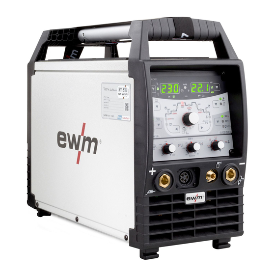
- Tetrix 230 AC/DC Comfort 8P TM
- Operating instructions manual
-
Contents
-
Table of Contents
-
Bookmarks
Quick Links
Operating instructions
Welding machine
EN
Tetrix 230 AC/DC Comfort 5P TM
Tetrix 230 AC/DC Comfort 8P TM
099-000159-EW501
16.08.2016
Related Manuals for EWM Tetrix 230 AC/DC Comfort 5P TM
Summary of Contents for EWM Tetrix 230 AC/DC Comfort 5P TM
-
Page 1
Operating instructions Welding machine Tetrix 230 AC/DC Comfort 5P TM Tetrix 230 AC/DC Comfort 8P TM 099-000159-EW501 16.08.2016… -
Page 2
+49 2680 181-0. A list of authorised sales partners can be found at www.ewm-group.com. Liability relating to the operation of this equipment is restricted solely to the function of the equipment. -
Page 3: Table Of Contents
Contents Notes on the use of these operating instructions Contents Contents …………………………3 Safety instructions ……………………..6 Notes on the use of these operating instructions …………….6 2.1.1 Explanation of icons ………………….. 7 …
-
Page 4
Contents Notes on the use of these operating instructions 5.10.8.3 Latched mode ………………..39 5.10.8.4 spotArc ………………….40 5.10.8.5 spotmatic ………………….. 42 5.10.9 TIG activArc welding ………………… 43 5.10.10 TIG antistick ……………………43 … -
Page 5
10.1 Parameter overview – setting information ………………. 80 10.1.1 TIG welding ……………………80 10.1.2 MMA welding …………………… 81 Appendix B ……………………….82 11.1 Overview of EWM branches ………………….82 099-000159-EW501 16.08.2016… -
Page 6: Safety Instructions
Safety instructions Notes on the use of these operating instructions Safety instructions Notes on the use of these operating instructions DANGER Working or operating procedures which must be closely observed to prevent imminent serious and even fatal injuries. • Safety notes include the «DANGER» keyword in the heading with a general warning symbol. •…
-
Page 7: Explanation Of Icons
Safety instructions Notes on the use of these operating instructions 2.1.1 Explanation of icons Symbol Description Symbol Description Indicates technical aspects which the Activate and release/tap/tip user must observe. Switch off machine Release/do not activate Switch on machine Press and hold switch Wrong Turn…
-
Page 8: General
Safety instructions General General WARNING Do not carry out any unauthorised repairs or modifications! To avoid injury and equipment damage, the unit must only be repaired or modified by specialist, skilled persons! The warranty becomes null and void in the event of unauthorised interference. •…
-
Page 9
Safety instructions General WARNING Risk of accidents due to non-compliance with the safety instructions! Non-compliance with the safety instructions can be fatal! • Carefully read the safety instructions in this manual! • Observe the accident prevention regulations and any regional regulations! •… -
Page 10
Safety instructions General CAUTION According to IEC 60974-10, welding machines are divided into two classes of electromagnetic compatibility (the EMC class can be found in the Technical data) > see 8 chapter: Class A machines are not intended for use in residential areas where the power supply comes from the low-voltage public mains network. -
Page 11
Safety instructions General Obligations of the operator! The respective national directives and laws must be observed for operation of the machine! • National implementation of the framework directive (89/391/EWG), as well as the associated individual directives. • In particular, directive (89/655/EWG), on the minimum regulations for safety and health protection when staff members use equipment during work. -
Page 12: Transport And Installation
Safety instructions Transport and installation Transport and installation WARNING Risk of injury due to improper handling of shielding gas cylinders! Improper handling and insufficient securing of shielding gas cylinders can cause serious injuries! • Observe the instructions from the gas manufacturer and any relevant regulations concerning the use of compressed air! •…
-
Page 13: Intended Use
In case of unauthorised changes, improper repairs, non-compliance with specified deadlines for «Arc Welding Equipment – Inspection and Testing during Operation», and/or prohibited modifications which have not been explicitly authorised by EWM, this declaration shall be voided. An original document of the specific declaration of conformity is included with every product.
-
Page 14: Machine Description — Quick Overview
Machine description – quick overview Front view Machine description – quick overview Front view Figure 4-1 Item Symbol Description Carrying handle Machine control, see the relevant control operating instructions Connection socket, 5-pole/8-pole/12-pole (depending on variant) 5-pole: Standard TIG torch control lead 8-pole: TIG Up/Down or potentiometer torch control lead 12-pole:…
-
Page 15: Rear View
Machine description – quick overview Rear view Rear view Figure 4-2 Item Symbol Description 8-pole connection socket Cooling unit control lead Ignition type changeover switch > see 5.10.7 chapter = —— Liftarc (contact ignition) = —— HF ignition Main switch, machine on/off Cooling air outlet Machine feet Mains connection cable >…
-
Page 16: Machine Control — Operating Elements
Machine description – quick overview Machine control – Operating elements Machine control – Operating elements The setting ranges for the parameter values are summarised in the Parameter overview section > see 10.1 chapter. Figure 4-3 Item Symbol Description Error/status indicators ———- Collective interference signal light >…
-
Page 17
Machine description – quick overview Machine control – Operating elements Item Symbol Description Welding current polarity button —— Direct current welding with positive polarity on the electrode holder in relation to the workpiece (pole reversal switch, MMA only). —— DC welding with negative polarity on the torch (or stick electrode holder) in relation to the workpiece. -
Page 18: Function Sequence
Machine description – quick overview Machine control – Operating elements 4.3.1 Function sequence Figure 4-4 Item Symbol Description Select welding parameters button This button is used to select the welding parameters depending on the welding process and operating mode used. Gas pre-flow time signal light AMP% Signal light…
-
Page 19: Design And Function
Design and function General Design and function General WARNING Risk of injury from electric shock! Contact with live parts, e.g. welding current sockets, is potentially fatal! • Follow safety instructions on the opening pages of the operating instructions. • Commissioning may only be carried out by persons who have the relevant expertise of working with arc welding machines! •…
-
Page 20: Transport And Installation
Design and function Transport and installation Transport and installation WARNING Risk of accident due to improper transport of machines that may not be lifted! Do not lift or suspend the machine! The machine can fall down and cause injuries! The handles and brackets are suitable for transport by hand only! •…
-
Page 21: Adjusting The Length Of The Carrying Strap
Design and function Machine cooling 5.2.2 Adjusting the length of the carrying strap To demonstrate adjustment, lengthening the strap is shown in the figure. To shorten, the strap’s loops must be inched in the opposite direction. Figure 5-1 Machine cooling Insufficient ventilation results in a reduction in performance and equipment damage.
-
Page 22: Notes On The Installation Of Welding Current Leads
Design and function Notes on the installation of welding current leads Notes on the installation of welding current leads Incorrectly installed welding current leads can cause faults in the arc (flickering). Lay the workpiece lead and hose package of power sources without HF igniter (MIG/MAG) for as long and as close as possible in parallel.
-
Page 23
Design and function Notes on the installation of welding current leads Fully unroll welding current leads, torch hose packages and intermediate hose packages. Avoid loops! Always keep leads as short as possible! Lay any excess cable lengths in meanders. Figure 5-4 Stray welding currents can destroy protective earth conductors, damage equipment and electronic devices and cause overheating of components leading to fire. -
Page 24: Mains Connection
Design and function Mains connection Mains connection DANGER Hazard caused by improper mains connection! An improper mains connection can cause injuries or damage property! • Only use machine with a plug socket that has a correctly fitted protective conductor. • If a mains plug must be fitted, this may only be carried out by an electrician in accordance with the relevant national provisions or regulations! •…
-
Page 25: Welding Torch Cooling System
Design and function Welding torch cooling system Welding torch cooling system 5.7.1 Welding torch cooling unit connection Please note the relevant documentation of the accessory components. Figure 5-7 Item Symbol Description 8-pole connection socket Cooling unit control lead 4-pole connection socket Cooling unit voltage supply Cooling module Control and supply lead to the welding machine…
-
Page 26: Tig Welding
Design and function TIG welding TIG welding 5.9.1 Welding torch and workpiece line connection Prepare welding torch according to the welding task in hand (see operating instructions for the torch). Figure 5-8 Item Symbol Description Welding torch Welding torch hose package Connection socket, «-«…
-
Page 27: Torch Connection Options And Pin Assignments
Design and function Shielding gas supply (shielding gas cylinder for welding machine) 5.9.1.1 Torch connection options and pin assignments Figure 5-9 5.10 Shielding gas supply (shielding gas cylinder for welding machine) WARNING Risk of injury due to improper handling of shielding gas cylinders! Improper handling and insufficient securing of shielding gas cylinders can cause serious injuries! •…
-
Page 28: Connecting The Shielding Gas Supply
Design and function Shielding gas supply (shielding gas cylinder for welding machine) 5.10.1 Connecting the shielding gas supply • Place the shielding gas cylinder into the relevant cylinder bracket. • Secure the shielding gas cylinder using a securing chain. Figure 5-10 Item Symbol Description Pressure regulator…
-
Page 29: Gas Test — Setting The Shielding Gas Volume
Design and function Shielding gas supply (shielding gas cylinder for welding machine) 5.10.2 Gas test – setting the shielding gas volume CAUTION Electric shocks! When setting the shielding gas quantity, high voltage ignition pulses or open circuit voltage are applied at the welding torch; these can lead to electric shocks and burning on contact.
-
Page 30: Welding Task Selection
Design and function Shielding gas supply (shielding gas cylinder for welding machine) 5.10.3 Welding task selection The tungsten electrode diameter setting has a direct effect on the machine functions. The set value should correspond to the tungsten electrode diameter. Obviously, the value can also be adjusted to different needs.
-
Page 31: Recurring Welding Tasks (Job 1-7)
Design and function Shielding gas supply (shielding gas cylinder for welding machine) 5.10.3.1 Recurring welding tasks (JOB 1–7) The user has 7 more memory locations at their disposal to save recurring or different welding tasks on a permanent basis. To do so, simply select the required memory location (JOB 1–7) and the welding task is set as described previously.
-
Page 32: Optimising The Ignition Characteristics For Pure Tungsten Electrodes
Design and function Shielding gas supply (shielding gas cylinder for welding machine) 5.10.4 Optimising the ignition characteristics for pure tungsten electrodes The best ignition and stabilisation of the arc (DC, AC) and optimum spherical cup formation in the tungsten electrode depend on the electrode diameter being used. The set value should correspond to the diameter of the tungsten electrode.
-
Page 33: Optimal And Fast Spherical Cup Formation
Design and function Shielding gas supply (shielding gas cylinder for welding machine) 5.10.5 Optimal and fast spherical cup formation Tungsten balling ensures optimum ignition and welding results for AC welding. A prerequisite for optimum tungsten balling is a sharpened electrode (approx. 15–25°). Tungsten balling should be performed on a test component as surplus tungsten may be melted and this may lead to impurities on the weld seam.
-
Page 34: Automatic Ac Frequency
Design and function Shielding gas supply (shielding gas cylinder for welding machine) 5.10.6 Automatic AC frequency 5.10.6.1 Manual, standard operation (JOB 0) EXIT Figure 5-17 Display Setting/selection AC frequency (AC) Automatic frequency Function enabled Setting via potentiometer Function disabled The AC frequency rotary knob is now without function. If it is turned nevertheless, the alternate flashing of parameters FrE and AUt on the control display shows the active function.
-
Page 35: Job Operation (Job 1 To 7)
Design and function Shielding gas supply (shielding gas cylinder for welding machine) 5.10.6.2 JOB operation (JOB 1 to 7) EXIT < Figure 5-18 Display Setting/selection Automatic frequency Function enabled 099-000159-EW501 16.08.2016…
-
Page 36: Arc Ignition
Design and function Shielding gas supply (shielding gas cylinder for welding machine) 5.10.7 Arc ignition The ignition type can be set at the ignition type changeover switch > see 5.10.7 chapter. 5.10.7.1 HF ignition The ignition energy can be adjusted, if required > see 5.15 chapter. Figure 5-19 The arc is started without contact from high-voltage ignition pulses.
-
Page 37: Function Sequences/Operating Modes
Design and function Shielding gas supply (shielding gas cylinder for welding machine) 5.10.8 Function sequences/operating modes 5.10.8.1 Explanation of symbols Symbol Meaning Press torch trigger 1 Release torch trigger 1 Current Time Gas pre-flows Ignition current Up-slope time Spot time Main current (minimum to maximum current) Secondary current AMP%…
-
Page 38: Non-Latched Mode
Design and function Shielding gas supply (shielding gas cylinder for welding machine) 5.10.8.2 Non-latched mode Figure 5-21 1st cycle: • Press torch trigger 1 and hold down. • Gas pre-flow time elapses. • HF ignition pulses jump from the electrode to the workpiece. The arc ignites. •…
-
Page 39: Latched Mode
Design and function Shielding gas supply (shielding gas cylinder for welding machine) 5.10.8.3 Latched mode Figure 5-22 cycle • Press torch trigger 1; gas pre-flow time elapses. • HF ignition pulses jump from the electrode to the workpiece. The arc ignites. •…
-
Page 40: Spotarc
Design and function Shielding gas supply (shielding gas cylinder for welding machine) 5.10.8.4 spotArc This process is suitable for tack welding or joint welding of metal sheets made from steel and CrNi alloys up to a thickness of approximately 2.5 mm. Metal sheets of different thicknesses can also be welded on top of one another.
-
Page 41
Design and function Shielding gas supply (shielding gas cylinder for welding machine) Figure 5-24 As an example the process is shown with HF ignition. Arc ignition with lift arc is also possible, however > see 5.10.7 chapter. Sequence: • Press torch trigger and hold down. •… -
Page 42: Spotmatic
Design and function Shielding gas supply (shielding gas cylinder for welding machine) 5.10.8.5 spotmatic This function must be enabled before use > see 5.15 chapter. In contrast to the spotArc operating mode, the arc is not ignited by pressing the torch trigger as is usual, but by briefly touching the tungsten electrode against the workpiece.
-
Page 43: Tig Activarc Welding
Shielding gas supply (shielding gas cylinder for welding machine) 5.10.9 TIG activArc welding The EWM activArc process, thanks to the highly dynamic controller system, ensures that the power supplied is kept virtually constant in the event of changes in the distance between the welding torch and the weld pool, e.g.
-
Page 44: Pulse Welding
Design and function Shielding gas supply (shielding gas cylinder for welding machine) 5.10.11 Pulse welding The following pulse types can be selected: • Thermal pulsing (TIG AC or TIG DC) • Metallurgical pulsing (TIG DC) • Automated pulsing (TIG DC) •…
-
Page 45
Design and function Shielding gas supply (shielding gas cylinder for welding machine) TIG pulses — latched operation Figure 5-30 Selection Figure 5-31 099-000159-EW501 16.08.2016… -
Page 46
Design and function Shielding gas supply (shielding gas cylinder for welding machine) Pulse time setting EXIT Figure 5-32 Pulse pause setting EXIT Figure 5-33 The pulse function can also be deactivated if necessary during the up-slope and down-slope phases (parameter ) >… -
Page 47: Metallurgical Pulsing (Khz Pulsing)
Design and function Shielding gas supply (shielding gas cylinder for welding machine) 5.10.11.2 Metallurgical pulsing (kHz pulsing) Metallurgical pulsing (kHz pulsing) uses the plasma force (arc force) occurring at high currents which allows you to achieve a constricted arc with concentrated heat input. Unlike thermal pulsing, no times are set;…
-
Page 48
Design and function Shielding gas supply (shielding gas cylinder for welding machine) Balance setting EXIT Figure 5-37 Frequency setting EXIT Figure 5-38 099-000159-EW501 16.08.2016… -
Page 49: Automated Pulses
Design and function Shielding gas supply (shielding gas cylinder for welding machine) 5.10.11.3 Automated pulses The automated pulses are used with tacking and spot welding of workpieces in particular. An oscillation in the molten pool is produced by the current-dependent pulse frequency and balance, which positively influences the ability to bridge the air gap.
-
Page 50: Ac Special
Design and function Shielding gas supply (shielding gas cylinder for welding machine) 5.10.11.5 AC special Figure 5-42 Application: e.g. for welding thick metal sheets onto thin metal sheets. AC current phase pulse current AMP% = DC phase pulse pause current Pulse time;…
-
Page 51: Welding Torch (Operating Variants)
Design and function Shielding gas supply (shielding gas cylinder for welding machine) 5.10.12 Welding torch (operating variants) Different torch versions can be used with this machine. Functions on the operating elements, such as torch triggers (TT), rockers or potentiometers, can be modified individually via torch modes.
-
Page 52: Standard Tig Torch (5-Pole)
Design and function Shielding gas supply (shielding gas cylinder for welding machine) 5.10.13.1 Standard TIG torch (5-pole) Standard torch with one torch trigger: Diagram Operating Explanation of symbols elements BRT1 = Torch trigger 1 (welding current on/off; secondary current via tapping function) Functions mode Operating…
-
Page 53
Design and function Shielding gas supply (shielding gas cylinder for welding machine) Standard torch with one rocker (MG rocker, two torch triggers) Diagram Operating Explanation of symbols elements BRT 1 = torch trigger 1 BRT 2 = torch trigger 2 Functions mode Operating… -
Page 54: Tig Up/Down Torch (8-Pole)
Design and function Shielding gas supply (shielding gas cylinder for welding machine) 5.10.13.2 TIG up/down torch (8-pole) Up/down torch with one torch trigger Diagram Operating Explanation of symbols elements TT 1 = torch trigger 1 Functions Mode Operating elements BRT 1 Welding current on/off BRT 1 Secondary current (tapping mode) / (Latched mode)
-
Page 55
Design and function Shielding gas supply (shielding gas cylinder for welding machine) Up/down torch with two torch triggers Diagram Operating Explanation of symbols elements TT 1 = torch trigger 1 (left) TT 2 = torch trigger 2 (right) Functions Mode Operating elements BRT 1… -
Page 56: Potentiometer Torch (8-Pole)
Design and function Shielding gas supply (shielding gas cylinder for welding machine) 5.10.13.3 Potentiometer torch (8-pole) The welding machine needs to be configured for operation with a potentiometer torch > see 5.10.13.4 chapter. Potentiometer torch with one torch trigger: Diagram Operating Explanation of symbols elements…
-
Page 57: Configuring The Tig Potentiometer Torch Connection
Design and function Shielding gas supply (shielding gas cylinder for welding machine) 5.10.13.4 Configuring the TIG potentiometer torch connection DANGER Risk of injury due to electrical voltage after switching off! Working on an open machine can lead to fatal injuries! Capacitors are loaded with electrical voltage during operation.
-
Page 58: Retox Tig Torch (12-Pole)
Design and function Shielding gas supply (shielding gas cylinder for welding machine) 5.10.13.5 RETOX TIG torch (12-pole) For machines with 12-pole torch connection socket only. Diagram Operating elements Explanation of symbols TT= torch trigger BRT 1 BRT 2 BRT 3 BRT 4 Functions Mode…
-
Page 59: Mma Welding
Design and function MMA welding 5.11 MMA welding CAUTION Risk of being crushed or burnt. When replacing spent or new stick electrodes • Switch off machine at the main switch • Wear appropriate safety gloves • Use insulated tongs to remove spent stick electrodes or to move welded workpieces and •…
-
Page 60: Welding Task Selection
Design and function MMA welding 5.11.2 Welding task selection It is only possible to change the basic parameters when no welding current is flowing and any possible access control is disabled > see 5.14 chapter. The welding task is selected using the buttons on the machine control on the welding machine. Signal lights (LED) display the welding parameter selection.
-
Page 61: Hotstart
Design and function MMA welding 5.11.3 Hotstart The hot start device ensures that stick electrodes ignite more effectively thanks to a greater hot start for the preset hot current. After selecting the stick electrode, the arc ignites with the hot start current start time and then reverts to the main current (AMP).
-
Page 62: Antistick
Design and function MMA welding 5.11.4 Antistick Anti-stick prevents the electrode from annealing. If the electrode sticks in spite of the Arcforce device, the machine automatically switches over to the minimum current within about 1 second to prevent the electrode from overheating. Check the welding current setting and correct according to the welding task! 5.11.5 Pulse welding Welding characteristics:…
-
Page 63
Design and function MMA welding EXIT Figure 5-51 099-000159-EW501 16.08.2016… -
Page 64: Remote Control
Design and function Remote control 5.12 Remote control The remote controls are operated on the 19-pole remote control connection socket (analogue). 5.12.1 RT1 19POL Functions • Infinitely adjustable welding current (0% to 100%) depending on the preselected main current on the welding machine. 5.12.2 RTG1 19POL Functions •…
-
Page 65: Interfaces For Automation
Design and function Interfaces for automation 5.13 Interfaces for automation 5.13.1 Remote control connection socket, 19-pole Damage to the machine due to improper connection! Unsuitable control leads or incorrect connection of input and output signals can cause damage to the machine. •…
-
Page 66: Power-Saving Mode (Standby)
Design and function Access control 5.13.2 Power-saving mode (Standby) You can activate the power-saving mode by either pressing the push-button > see 4.3 chapter for a prolonged time or by setting a parameter in the machine configuration menu (time-controlled power- saving mode) >…
-
Page 67
Design and function Machine configuration menu Figure 5-53 099-000159-EW501 16.08.2016… -
Page 68
Design and function Machine configuration menu Display Setting/selection Lock JOB menu Protect welding parameters from unauthorised access. Machine code Querying the three-digit machine code (000 to 999), user input Error Error message after entering an incorrect machine code Switch on Switching on machine function Switch off Switching off machine function… -
Page 69
Design and function Machine configuration menu Negative welding current polarity during the ignition phase Positive welding current polarity during the ignition phase Service menu Service settings Machine fan test Machine fan is switched off Machine fan test Machine fan is switched on Software version of the machine control Version display (example 014 = version 14) Mains current limit… -
Page 70: Maintenance, Care And Disposal
Maintenance, care and disposal General Maintenance, care and disposal General DANGER Incorrect maintenance and testing! The machine may be cleaned, repaired and tested by skilled and qualified personnel only. A qualified person is one who, due to their training, knowledge and experience, can detect any hazards and possible consequential damage when checking the machine, and can take the necessary safety measures.
-
Page 71: Maintenance Work, Intervals
Maintenance, care and disposal Maintenance work, intervals Maintenance work, intervals Repair and maintenance work may only be performed by qualified authorised personnel; otherwise the right to claim under warranty is void. In all service matters, always consult the dealer who supplied the machine.
-
Page 72: Annual Test (Inspection And Testing During Operation)
In addition to this, returns are also possible throughout Europe via EWM sales partners. Meeting the requirements of RoHS We, EWM AG Mündersbach, hereby confirm that all products supplied by us which are affected by the RoHS Directive, meet the requirements of the RoHS (Directive 2011/65/EU).
-
Page 73: Rectifying Faults
Rectifying faults Checklist for rectifying faults Rectifying faults All products are subject to rigorous production checks and final checks. If, despite this, something fails to work at any time, please check the product using the following flowchart. If none of the fault rectification procedures described leads to the correct functioning of the product, please inform your authorised dealer.
-
Page 74
Rectifying faults Checklist for rectifying faults No arc ignition Incorrect ignition type setting. Ignition type: Select “HF start”. Depending on the machine, the setting is defined by the changeover switch for ignition types or the parameter in one of the machine menus (see the “Control operating instructions”, if applicable). -
Page 75: Machine Faults (Error Messages)
Rectifying faults Machine faults (error messages) Machine faults (error messages) A welding machine error is indicated by the collective fault signal lamp (A1) lighting up and an error code (see table) being displayed in the machine control display. In the event of a machine error, the power unit shuts down.
-
Page 76: Resetting Welding Parameters To The Factory Settings
Rectifying faults Resetting welding parameters to the factory settings Resetting welding parameters to the factory settings All customised welding parameters that are stored will be replaced by the factory settings. RESET Figure 7-1 Display Setting/selection Input confirmation User entries are applied, release button(s). 099-000159-EW501 16.08.2016…
-
Page 77: Vent Coolant Circuit
Rectifying faults Vent coolant circuit Vent coolant circuit To vent the cooling system always use the blue coolant connection, which is located as deep as possible inside the system (close to the coolant tank)! blau / blue ca. 5s KLICK CLICK KLICK CLICK…
-
Page 78: Technical Data
Technical data Tetrix 230 AC/DC Technical data Performance specifications and guarantee only in connection with original spare and replacement parts! Tetrix 230 AC/DC Setting range Welding current 3 A–230 A 5 A–180 A 5 A–230 A Welding voltage 10.1 V–19.2 V 20.2 V–27.2 V Duty cycle (DC) at 40 °C 40% DC…
-
Page 79: Accessories
Accessories Remote controls and accessories Accessories Performance-dependent accessories like torches, workpiece leads, electrode holders or intermediate hose packages are available from your authorised dealer. Remote controls and accessories Type Designation Item no. RTF1 19POL 5 M Foot-operated remote control current with 094-006680-00000 connection cable RT1 19POL…
-
Page 80: Parameter Overview — Setting Information
Appendix A Parameter overview – setting information Appendix A 10.1 Parameter overview – setting information 10.1.1 TIG welding Parameter Display Setting range Comment TIG/plasma Main current Gas pre-flow time Ignition current AMP% % of main current AMP Up-slope time 20,0 Pulse time 0,01 — 9,99…
-
Page 81: Mma Welding
Appendix A Parameter overview – setting information 10.1.2 MMA welding Parameter Display Setting range Comment Main current Hot start current Hot start time Pulse current Pulse frequency Pulse balance 099-000159-EW501 16.08.2016…
-
Page 82: Overview Of Ewm Branches
Appendix B Overview of EWM branches Appendix B 11.1 Overview of EWM branches 099-000159-EW501 16.08.2016…
File Specifications:1250/1250347-tetrix_230_acdc_comfort_5p_tm.pdf file (18 Aug 2023) |
Accompanying Data:
EWM Tetrix 230 AC/DC Comfort 8P TM Welding System PDF Operating Instructions Manual (Updated: Friday 18th of August 2023 06:27:01 PM)
Rating: 4.8 (rated by 41 users)
Compatible devices: PICO 230 CEL, Tetrix 300 DC Smart 2.0 puls, Taurus XQ 355 Synergic, inverter STICK 250 H-2, Pico 350 cel puls pws MMA, Picomig 180 Synergic TGE, TETRIX 1002 DC SYNERGIC, Saturn 301 FKG.
Recommended Documentation:
Operating Instructions Manual (Text Version):
(Ocr-Read Summary of Contents of some pages of the EWM Tetrix 230 AC/DC Comfort 8P TM Document (Main Content), UPD: 18 August 2023)
-
EWM Tetrix 230 AC/DC Comfort 8P TM User Manual
-
EWM Tetrix 230 AC/DC Comfort 8P TM User Guide
-
EWM Tetrix 230 AC/DC Comfort 8P TM PDF Manual
-
EWM Tetrix 230 AC/DC Comfort 8P TM Owner’s Manuals
Recommended: Color LaserJet CM1312nfi MFP, 50, ED-X24 and, A02-WRA4-54G
Links & Tools
-
BRUKSANVISNINGUSER GUIDEBETRIEBSANLEITUNGGUIDE DE L’UTILISATEURBRUGSVEJLEDNINGGUIDA PER L’UTILIZZATOREGEBRUIKERSHANDLEIDINGKÄYTTÖOHJEGUÍA DE USUARIOKEZELÉSI ÚTMUTATÓPODRĘCZNIK UŻYTKOWNIKACMI3000 II50115052 Valid from 2017 week 20 …
CMI3000 II 92
-
WF 230 ClassicWF 230 SmartWF 230 Exclusive ISTRUZIONI PER L’USO INSTRUCTION MANUAL BETRIEBSANWEISUNG MANUEL D’INSTRUCTIONS INSTRUCCIONES DE USO MANUAL DE INSTRUÇÕESGEBRUIKSAANWIJZINGBRUKSANVISNINGBRUGERVEJLEDNINGBRUKSANVISNINGKÄYTTÖOHJEETOΔΗΓΙΕΣ ΧΡΗΣΗΣ …
WF 230 Classic 284
-
EN1LINCGUN® PROMIG™ ManualWATER COOLEDW000345063-2 LINCGUN PROMIG 330W 3MW000345064-2 LINCGUN PROMIG 330W 4MW000345065-2 LINCGUN PROMIG 330W 5MW000345069-2 LINCGUN PROMIG 400W 3MW000345070-2 LINCGUN PROMIG 400W 4MW000345071-2 LINCGUN PROMIG 400W 5MW000345075-2 LINCGUN PROMIG 500W 3MW000345076-2 LINCGUN PRO …
LINCGUN PROMIG W000345063-2 8
-
OPERATING MANUALMULTI PROCESS WELDING INVERTERVersion No: AB | Issue Date: 03-02-2019 | Manual No: 0-5550INPUT SUPPLY240V 15A*SAFETY DEVICEOUTPUT CURRENT255ADC*INT. WIRE FEEDERSPOOLS UP TO 300mmTransmig 255iTransmig 255i*Refer to Specification Table for rating information. …
CIGWELD Transmig 255i 96
Operating Impressions, Questions and Answers:
-
Grizzly H8155
MODEL H8155MIG WELDEROWNER’S MANUALCOPYRIGHT © MAY, 2007 BY GRIZZLY INDUSTRIAL, INC.WARNING: NO PORTION OF THIS MANUAL MAY BE REPRODUCED IN ANY SHAPE OR FORM WITHOUT THE WRITTEN APPROVAL OF GRIZZLY INDUSTRIAL, INC. #LO9344 PRINTED IN CHINA …
H8155 Welding System, 24
-
bester 151
IM2028Effective with the Serial Number:Process MMA WeldingScratch TIG (B 151 I)Lift TIG (B 181/210 I)Description Welding InverterOperator’s Manual / Instrukcja obsługiBester-151 InverterBester-181 InverterBester-210 InverterENG/POL07/2009 (rev00)LE BESTER SAul.Jana III Sobieskiego 19APL 58-263 BielawaTel.+48 (0)74 …
151 Welding System, 20
-
Lincoln Electric Power MIG 350MP
Power MIG®. The Professional’s ChoiceSM.When you need more than just a MIG machine, the Power MIG®350MP isthe choice for you. Lincoln Chopper Technology®delivers more weldingprocesses—MIG and flux-cored, along with excellent stick welding, TIG andadvanced processes such as Power Mode™and Pulse-on-Pulse®. In a …
Power MIG 350MP Welding System, 8
-
Forney 242
WWW.FORNEYIND.COM242 DUAL MIG WELDER OPERATING MANUALFEATURES:• 240A Output• 230V Input• Heavy-Duty torch• Aluminum drive system• Welds steel or aluminum with only the flip of a switch• 2 Euro connects; 1 dedicated to spool gun• Easy to use, increases productivity• Digital readout for true amps� …
242 Welding System, 81
-
NewArc rt2500
Processes Description Newarc Ltd. UK‘s Leading Manufacturer Of Welding Equipment Newcastle +44 (0) 191 295 0111 Aberdeen +44 (0) 1224 771 063 www.newarc.co.uk To maintain continued developments of our products we reserve the right to alter specifications as quoted without prior notice RT2500 Important Information …
rt2500 Welding System, 12
-
Chicago Electric 62486
Visit our website at: http://www.harborfreight.com Email our technical support at: [email protected]’s Manual & Safety InstructionsSave This Manual Keep this manual for the safety warnings and precautions, assembly, operating, inspection, maintenance and cleaning procedures. Write the product …
62486 Welding System, 28
-
Kaliburn SR-45i
SR-45i User’s Manual SR-45i Plasma Cutting System Revision 11 5/16/07 Manual Part Number 718061 455 Fleming Road Charleston, SC 29412 USA (800) 252-2850 – Toll free (843) 795-4286 – Phone (843) 795-8931 – Fax www.kaliburn.net …
SR-45i Welding System, 71
-
Grizzly G4176
MODEL G4176 1⁄4 HP POWER FEEDEROWNER’S MANUAL(For models manufactured since 5/14)COPYRIGHT © JUNE, 2008 BY GRIZZLY INDUSTRIAL, INC. REVISED APRIL, 2014 (TS)WARNING: NO PORTION OF THIS MANUAL MAY BE REPRODUCED IN ANY SHAPE OR FORM WITHOUT THE WRITTEN APPROVAL OF GRIZZLY INDUSTRIAL, INC. #CR10815 PRINTED IN TAIW …
G4176 Accessory, 36