Quick Reference Guide
This Quick Reference Guide will
assist you in finding the information
you’re looking for.
A Table of Contents is included after
the Foreword.
SAFETY INFORMATION j
GENERAL INFORMATION j
HOW TO RIDE THE MOTORCYCLE j
MAINTENANCE AND ADJUSTMENT j
APPENDIX j
MAINTENANCE RECORD j
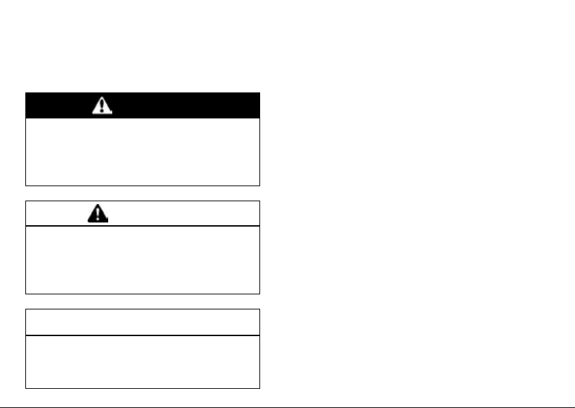
Whenever you see the symbols
shown below, heed their instructions!
Always follow safe operating and maintenance practices.
DANGER
DANGER indicates a hazardous
situation which, if not avoided,
will result in death or serious in-
jury.
WARNING
WARNING indicates a hazardous
situation which, if not avoided,
could result in death or serious
injury.
NOTICE
NOTICE is used to address prac-
tices not related to personal in-
jury.
NOTE
NOTE indicates information that may
○
help or guide you in the operation or
service of the vehicle.

NOTICE
THIS PRODUCT HAS BEEN
MANUFACTURED FOR US E IN A
REASONABLE AND PRUDENT
MANNER BY A QUALIFIED OPERATOR AND AS A VEHICLE
ONLY.

Foreword
Congratulations on your purchase of a new Kawasaki motorcycle. Your new motorcycle is the product of Kawasaki’s advanced engineering, exhaustive testing,
and continuous striving for superior reliability, safety and p e rfo rmance.
Please read this Owner ’s Manual carefully before riding so that you will be
thoroughly familiar with the proper operation of your motorcycle’s controls, its features, capabilities, and limitations. This manual offers many safe riding tips, but its
purpose is n ot to provide instruction in all the techniques and skills required to ride
a motorcycle safely. Kawasaki strongly recommends that all operators of this vehicle enroll in a motorcycle rider training program to attain awareness of the mental
and physical requirements necessary for safe motorcycle operation.
To ensure a long, trouble-free life for your motorcycle, give it the proper care and
maintenance described in this manual. For those who would like more detailed information on their Kawasaki Motorcycle, a Service Manual is available for purchase
from any authorized Kawasaki motorcycle dealer. The Service Manual contains detailed disassembly and maintenance information. Those who plan to do their own
work should, of course, be competent mechanics and possess the special tools
described in the Service Manual.
Keep this Owner’s Manual aboard your motorcycle at all times so that you can
refer to it whenever you need information.

This manual should be considered a permanent part of the motorcycle and should
remain with the motorcycle when it is sold.
All rights reserved. No part of this publication may be reproduced without our
prior written permission.
This publication includes the latest information available at the time of printing.
However, there may be minor differences be twee n the actual product and illustrations and text in this manual.
All products are subject to change without prior notice or obligation.
KAWASAKI HEAVY INDUSTRIES, LTD.
Motorcycle & Engine Company
© 2014 Kawasaki H eavy Industries, Ltd. Mar. 21, 2014. (1)

(Australian model only)
TAMPERING WITH NOISE CONTROL SYSTEM
PROHIBITED
Owners are warned that the law may prohibit:
(a) The removal or rendering inoperative by any person other than for purposes
of maintenance, repair or replacement, of any device or element of design
incorporated into any new vehicle for the purpose of noise control prior to
its sale or delivery to the ultimate purchaser or while it is in use; and
(b) The use of the vehicle after such device or element of design has been
removed or rendered inoperative by any person.

TABLE OF CONTENTS
SAFETY INFORMATION ……………….. 10
Read Owner’s Manual ………………… 10
Training …………………………………….. 10
Daily Checks and Periodic
Maintenance …………………………… 10
Loading and Accessories
Information……………………………… 11
Passenger ……………………………… 12
Baggage and Luggage …………….. 13
Accessories ……………………………. 13
Other Load……………………………… 14
If You are Involved in an A ccident…. 14
Safe Operation …………………………… 15
Carbon Monoxide Hazard…………. 15
Fueling…………………………………… 16
Never Ride with Drugs or Alcohol. 16
Protective Gear and Clothing ……. 16
Safe Riding Techniques……………. 17
Additional Con siderations for High
Speed Operation ………………….. 19
GENERAL INFORMATION…………….. 21
Specifications…………………………….. 21
Serial Number Locations……………… 26
Location of Labels ………………………. 27
Location of Parts ………………………… 37
Meter Instruments ………………………. 40
Indicators ……………………………….. 41
Speedometer/Tachometer ………… 49
Coolant Temperature Meter/Clock 50
Display Setting………………………… 53
Features ………………………………… 58
Keys …………………………………………. 60
Ignition Switch/Steering Lock ……….. 63
Right Handlebar Switches……………. 65
Left Handlebar Switches ……………… 66
Brake Lever Adjuster…………………… 67
Fuel Tank Cap ……………………………. 68
Fuel ………………………………………….. 69
Fuel Requirements ………………….. 69
Filling the Tank………………………… 72

Side Stand ………………………………… 74
Seats………………………………………… 74
Tying Hooks ………………………………. 76
Helmet Cables (Southeast Asia B2
model only) …………………………….. 77
Tool Kit ……………………………………… 78
Windshield…………………………………. 78
Event Data Recorder…………………… 81
HOW TO RIDE THE MOTORCYCLE .82
Break-In ……………………………………. 82
Starting the Engine …………………….. 83
Jump Starting …………………………….. 86
Moving Off…………………………………. 88
Shifting Gears ……………………………. 89
Braking……………………………………… 90
Anti-lock Brake System (ABS) ……… 91
Stopping the Engine……………………. 94
Stopping the Motorcycle in an
Emergency …………………………….. 94
Parking……………………………………… 95
Kawasaki TRaction Control (KTRC). 97
Power Mode ………………………………. 101
KTRC and Power Mo de
Combination …………………………… 103
MAINTENANCE AND ADJUSTMENT 105
Daily Checks ……………………………… 107
Periodic Maintenance………………….. 110
Engine Oil …………………………………. 115
Coolant……………………………………… 119
Air Cleaner ………………………………… 121
Throttle Control System ………………. 122
Idle Speed …………………………………. 125
Clutch……………………………………….. 126
Drive Chain ……………………………….. 127
Brakes………………………………………. 130
Brake Light Switches…………………… 132
Suspension System ……………………. 135
Front Fork ………………………………. 135
Rear Shock Absorber ………………. 138
Setting Tables…………………………. 141
Wheels ……………………………………… 145
Battery………………………………………. 149
Headlight…………………………………… 152
Fuses ……………………………………….. 153
General Lubrication…………………….. 155

Cleaning Your Motorcycle ……………. 156
General Precautions ………………… 156
Washing Your Motorcycle …………. 158
APPENDIX …………………………………… 162
Storage …………………………………….. 162
Troubleshooting Guide………………… 165
OWNER SATISFACTION…………….. 166
Environmental Protection …………….. 168
MAINTENANCE RECORD …………….. 169
10 SAFETY INFORMATION
SAFETY INFORMATION
Read Owner’s Manual
Read this Owner’s Manual carefully before riding so that you will be
thoroughly familiar with the proper operation of your motorcycle’s controls,
its fe ature s, capabilities, and limitations. This manual offers many safe
riding tips, but its purpose is not to provide instruction in all of the techniques
and skills required to ride a motorcycle
safely.
Training
Kawasaki strongly recommends that
all operators of this vehicle complete a
suitable motorcycle rider training program to learn the proper skills and techniques necessary for safe motorcycle
operation.
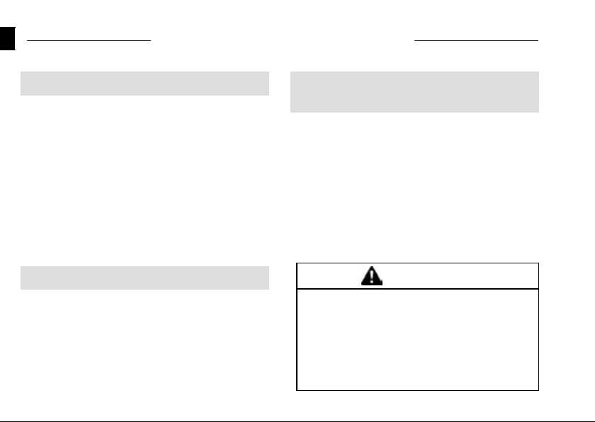
DailyChecksandPeriodic
Maintenance
It is important to keep your motorcycle properly maintained and in safe riding condition. Inspect your motorcycle before every ride and carry out all
periodic maintenance. See the Daily
Checks section and the Periodic Maintenance section in the MAINTENANCE
AND ADJUSTMENT chapter for more
information.
WARNING
Failure to perform these checks
or to correct a problem before
operation may result in serious
damage or an accident. Always
perform daily checks before op-
eration.
SAFETY INFORMATION 11
To ensure your motorcycle is serviced using the latest servicing information, it is recommended that an
authorized Kawasaki Dealer performs
the periodic maintenance as directed
in the Owner’s Manual.
If you notice any irregular operating condition, have your motorcycle
thoroughly checked at an authorized
Kawasaki dealer as soon as possible.
Loading and Accessories
Information
WARNING
Incorrect loading, improper installation or use of accessories
or modification of your motorcycle may result in an unsafe riding
condition. Before you ride the
motorcycle,makesureitisnot
overloaded and that you have
followed these in structions.
Maximum L oad
Weight of rider, passenger, baggage,
and accessories must not exceed 195 kg
(430 lb).
With the exception of genuine
Kawasaki Parts a nd Accessories,
Kawasaki has no control over the
design or application of accessories.
In some cases, improper installation

12 SAFETY INFORMATION
or use of accessories, or motorcycle
modification, will void the motorcycle
warranty; can negatively affect performance, stability and safety; and can
even be illegal.
In selecting and using accessories,
and in loading the motorcycle, you are
personally responsible for your own
safety and the safety of other persons
involved.
NOTE
Kawasaki Parts and Accessories
○
have been specially designed for
use on Kawasaki motorcycles. We
strongly recommend that all parts
and accessories you add to your
motorcycle be genuine Kawasaki
components.
Because a motorcycle is sensitive to
changes in weight and aerodynamic
forces, you must take extreme care in
carrying cargo, passengers and/or in
fitting additional accessories. The following general guidelines have been
prepared to assist you in m aking your
determinations.
Passenger
1. Never carry more than one passenger.
2. The passenger should only sit on the
pillion.
3. Any passenger should be thoroughly familiar with motorcycle operation. The passenger can affect
control of the motorcycle by improper positioning during cornering
and sudden movements. It is important that the passenger sits still
while the motorcycle is in motion
and not interfere with the operation
of the motorcycle. Do not carry animals on your motorcycle.

SAFETY INFORM ATION 13
4. Do not carry passengers unless
passenger footpegs are installed.
Instruct any passenger before riding
to keep his or her feet on the passenger footpegs and hold on to the
operator or seat strap. Do not carry
a passenger unless he or she is tall
enough to reach the footpegs with
their feet.
Baggage and Luggage
1. All baggage should be carried as
low as possible to reduce the effect
on the motorcycle’s center of gravity. Baggage weight should also be
distributed equally on both sides of
the motorcycle. Avoid carrying baggage that extends beyond the rear
of the motorcycle.
2. Baggage should be securely attached. Make sure that the baggage
will not move around while you are
riding. Recheck baggage security
as often as possible (not while the
motorcycle is in motion) and adjust
as necessary.
3. Do not carry heavy or bulky items
on a luggage rack. It is designed
for light items, and overloading can
affect handling due to changes in
weight distribution and aerodynamic
forces.
Accessories
1. Do not install accessories or carry
baggage that impairs the performance of the motorcycle. Make
sure that you have not adversely
affected any lighting components,
road clearance, banking capability
(i.e., lean angle), control operation,
wheel travel, front fork movement,

14 SAFETY INFORMATION
or any other aspects of the motorcycle’s operation.
2. Weight attached to the handlebars
or front fork will increase the mass
of the steering assembly and can
result in an unsafe riding condition.
3. Fairings, windshields, backrests,
and other large items have the capability of adversely affecting stability and handling of the motorcycle,
not only due to their weight, but
also due to the aerodynamic force
acting on these surfaces while the
motorcycle is in operation. Poorly
designed or installed items can result in an unsafe riding condition.
Other Load
1. This motorcycle is not intended to
be equipped with a sidecar or to be
used to tow any trailers or other vehicles. Kawasaki does not manufacture sidecars or trailers for motorcycles and cannot predict the effects of such accessories on handling or stability, but can only warn
thattheeffectscanbeadverseand
that Kawasaki cannot assume responsibility for the results of such
unintended use of the motorcycle.
2. Furthermore, any adverse effects on
motorcycle components caused by
the use of such accessories will not
be remedied under warranty.
If You are Involved in an
Accident
Make sure of your own safety first.
Determine the severity of any injuries
and call for emergency assistance if
needed. Always follow applicable laws
and regulations if any other person, vehicle or property is involved.
Do not attempt to continue riding
without first evaluating your motorcycle’s condition. Inspect for fluid leaks,
check critical nuts and bolts, and check
the handlebars, control levers, brakes,
and wheels for damage and proper
function. Ride slowly and cautiously
— your motorcycle may have suffered
damage that is not immediately apparent. Have your motorcycle thoroughly
checked at a Kawasaki dealer as soon
as possible.
Safe Operation
The following should be carefully observed for safe and effective vehicle
operation.
SAFETY INFORM ATION 15
Carbon Monoxide Hazard
DANGER
Exhaust gas contains carbon
monoxide, a colorless, odorless
poisonous gas. Inhaling carbon
monoxide can cause serious
brain injury or death.
Do not run the engine in enclosed areas. Operate only in a
well-ventilated area.
16 SAFETY INFORMATION
Fueling
WARNING
Gasoline is extremely flammable
and can be explosive under certain conditions.
To avoid a possible fire or explosion, turn the ignition switch to
“OFF.” Do not smoke. Make sure
theareaiswellventilatedand
free from any source of flame or
sparks; this includes any appliance with a pilot light.
Never Ride with Drugs or Alcohol
Alcohol and drugs impair your judgment and reaction time. Never consume alcohol or drugs before or while
riding motorcycles.
Protective Gear and Clothing
Helmet
Kawasaki strongly recommends both
the operator and passenger wear a helmet even if this is not a legal requirement.
— Make sure that your helmet fits cor-
rectly and is properly fastened.
— Choose a mot orcycle helm et that
meets the safety standards applicable to your country. Ask your
motorcycle dealer to advise you if
necessary.

SAFETY INFORM ATION 17
Eye Protection
Always use eye protection. If your
helmet does not have a v isor installed,
wear goggles.
Gloves
Wear gloves which have suitable
protection for your hands, especially
against abrasion.
Clothing
Wear protective clothing.
— Wear bright, highly visible cloth ing
that allows freedom of movement
to suit your riding style.
— Always wear a long- s lee ve d jacket
and long t ro users w hich a re abrasion resistant and keep you warm.
— Avoid wearing clothes which have
loose cuffs or other fastenings
which could interfere with the controls of your motorcycle.
Boots
Wear proper protective boots that fit
properly and do not interfere with gear
shifting or braking.
Safe Riding Techniques
Keep Hands on Handlebars
When riding always keep both hands
on the handlebars and both feet on the
footpegs. Removing your hands from
the handlebars or feet from the footpegs while riding can be hazardous. If
you remove even one hand or foot, you
reduce your ability to control the motorcycle.
Look Over Your Shoulder
Before changing lanes, look over
your shoulder to make sure the way
is clear. Do not rely solely on the rear

18 SAFETY INFORMATION
view mirror; you may misjudge a vehicle’s distance and speed, or you may
not see it at all.
Accelerate and Brake Smoothly
In general your actions should be
smooth as sudden acceleration, braking or turning may caus e loss of control,
especially when riding in wet conditions
or on loose road surfaces, when the
ability to maneuver will be reduced.
Select Correct Gear Speeds
When going up steep slopes, shift to
a lower gear so that there is power to
spare rather than overloading the engine.
Use Both Front and Rear Brakes
When applying the brakes, use both
the front and rear brakes. Applying
only one brake for sudden braking may
cause the motorcycle to skid and lose
control.
Use Engine Brake
When going down long slopes, help
control vehicle speed by closing the
throttle so that the engine can act as an
auxiliary brake. Use the front and rear
brakes for primary braking.
Riding in Wet Conditions
Rely more on the throttle to control
vehicle speed and less on the front and
rear brakes. The throttle should also be
used judiciously to avoid skidding the
rear wheel from too rapid acceleration
or deceleration.
Braking performance is also reduced
in wet conditions. Carefully ride at a
slow speed and apply the brakes several times to help dry and restores them
to normal operating performance.
Lubricate the drive chain after wet
-weather riding to prevent rust and corrosion.
SAFETY INFORM ATION 19
Ride Prudently
Riding at the proper speed and avoiding unnecessarily fast acceleration are
important not only for safety and low
fuel consumption but also for long vehicle life and quieter operation.
Riding on Rough Roads
Exercise caution, slow down, and
grip the fuel tank with the knees for
better stability.
Acceleration
When quick acceleration is necessary to pass another vehicle, shift to
a lower gear to obtain the necessary
power.
Downshifting
To avoid engine damage and rear
wheel lock-up do not downshift at high
rpm.
Avoid Unnecessary Weaving
Unnecessary weaving jeopardizes
the safety of both the rider and other
motorists.
Additional Considerations for
High Speed Operation
WARNING
Handling characteristics of a
motorcycle at high speeds m ay
vary from those you are familiar
with at legal highway speeds.
Do not attempt high speed oper-
ation unless you have received
sufficient training and have the
required skills.
Do not operate at high speeds on
public roads.

20 SAFETY INFORMATION
Brakes
The importance of the brakes, especially during high speed operation,
cannot be overemphasized. Check to
see that they are correctly adjusted and
functioning properly.
Steering
Looseness in the steering can cause
loss of control. Check to see that the
handlebars turns freely but has no play.
Tires
High speed operation is hard on tires,
and good tires are crucial for safe riding. Examine their overall condition, inflate them to the proper pressure, and
check the wheel balance.
Fuel
Have sufficient fuel for the high fuel
consumption during high speed operation.
Engine Oil
To avoid engine s eizure and resulting
loss of control, make sure that the oil
level is at the upper level line.
Coolant
To avoid overheating, check that the
coolant level is at the upper level line.
Electrical Equipment
Make sure that the headlight,
tail/brake light, turn signals, horn, etc.,
all work properly.
Miscellaneous
Make sure that all nuts and bolts are
tight and that all safety related parts are
in good condition.

Specifications
GENERAL INFORMATION 21
GENERAL INFORMATION
PERFORMAN
Maximum Horsepower
Maximum Torque
Minimum Turning Radius
DIMENSI
Overal
Overal
Overal
Wheelbase
Road C
CE
(SEA-B1/B2, TH) 100.9 kW (137 PS) @9 800 r/min (rpm)
(SEA-B1/B2, TH) 109 N·m (11.1 kgf·m, 80 ft·lb) @7 300 r/min (rpm)
ONS
l Length
lWidth
l Height/High Position
learance
104.5 kW (142 PS) @10 000 r/min (rpm)
111N·m(11.3kgf·m,82ft·lb)@7300r/min(rpm)
3.1 m (12
2105mm
790 mm (
1170mm
1445mm
135 mm
2in.)
(82.9 in.)
31.1 in.)
(46.1 in.)/1 230 mm (48.4 in.)
(56.9 in.)
(5.3 in.)

22 GENERAL INFORMATION
Curb Mass
ENGINE
Type DOHC, 4-cylinder, 4-stroke, liquid-cooled
Displacement 1 043 cm³ (63.6 cu in.)
Bore × Stroke 77.0 × 56.0 mm (3.0 × 2.2 in.)
Compression Ratio 11.8:1
Starting System Electric starter
Cylinder Numbering Method Left to right, 1-2-3-4
Firing Order 1-2-4-3
Fuel System FI (Fuel Injection)
Ignition System Battery and coil (transistorized ignition)
on Timing
Igniti
(Electronically advanced)
Spark Plug:
Lubrication System Forced lubrication (wet sump)
(ZX1000L) 230 kg (507 lb)
(ZX1000M) 231 kg (509 lb)
10° BTDC @1 100 r/min (rpm) ∼ 40.2° BTDC @5 200
r/min (rpm)
Type
Gap 0.8 ∼ 0.9 mm (0.031 ∼ 0.035 in.)
NGK CR9EIA-9

GENERAL INFORMATION 23
Engine Oil: Type API SG, SH, SJ, SL or SM with JASO MA, MA1 or MA2
Viscosity SAE 10W-40
Capacity 4.0 L (4.2 US qt)
Coolant Capacity 2.9 L (3.1 US qt)
TRANSMISSION
Transmission Type 6-speed, constant mesh, return shift
Clutch Type Wet, multi disc
Driving System Chain drive
Primary Reduction Ratio 1.627 (83/51)
Final Reduction Ratio 2.733 (41/15)
Overall Drive Ratio 4.925 (Top gear)
Gear Ratio: 1st 2.600 (39/15)
2nd 1.950 (39/20)
3rd 1.600 (24/15)
4th 1.389 (25/18)
5th 1.238 (26/21)
6th 1.107 (31/28)

24 GENERAL INFORMATION
FRAME
Caster 24.5°
Trail 102 mm (4.0 in.)
Tire Size: Front 120/70ZR17 M/C (58W)
Rear 190/50ZR17 M/C (73W)
Rim Size: Front J17M/C × MT3.50
Rear J17M/C × MT6.00
Fuel Tank Capacity 19 L (5.0 US gal)
Brake Fluid: Front DOT4
Rear DOT4
ELECTRICAL EQUIPMENT
Battery 12V10Ah(10HR)
Headlight: High Beam 12 V 55 W × 2
Low Beam 12 V 55 W
Tail/Brake Light LED
SEA-B1: Southeast Asia B1 model (with Evaporative Emission Control System)
SEA-B2: Southeast Asia B2 model

GENERAL INFORMATION 25
TH: Thailand model
Even if one of LED (Light Emitting Diode) tail/brake light does not go on, consult
with an authorized Kawasaki dealer.
Specifications are subject to change without notice, and may not apply to every
country.
26 GENERAL INFORMATION
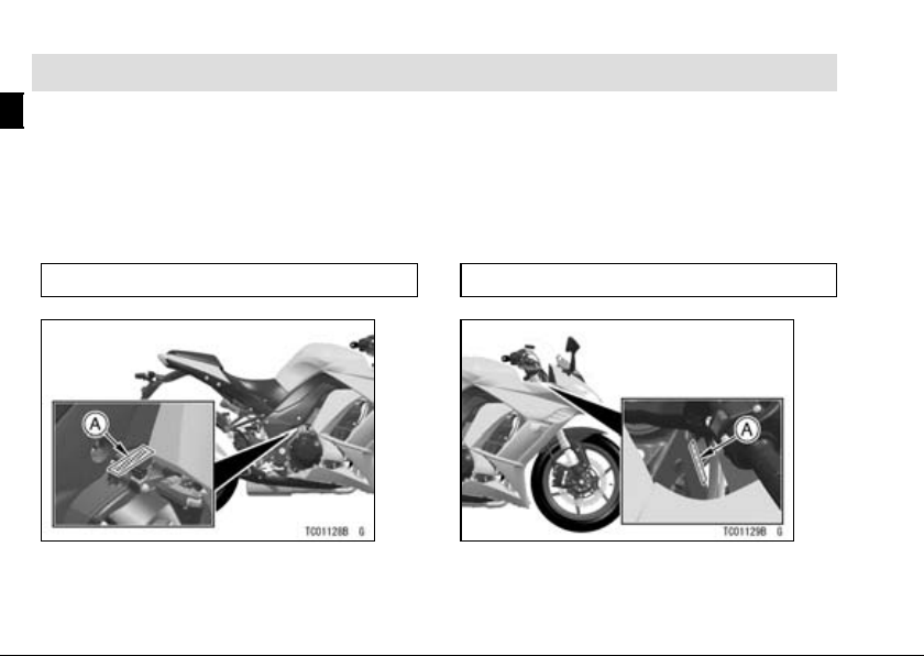
Serial Number Locations
The engine and frame serial numbers are used to register the motorcycle. They
are the only means of identifying your particular machine from others of the same
model type. These s erial numbers may be needed by your dealer when ordering
parts. In the event of theft, the investigating authorities will require both numbers
as well as the model type and any peculiar features of your machine that can help
them identify it.
Engine No.
A. Engine Number
Frame No.
A. Frame Number
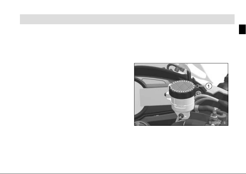
Location of Labels
All warning labels which are on your
vehicle are repeated here. Read labels
on your vehicle and understand them
thoroughly. They contain information
which is important for your safety and
the safety of anyone else who may operate your vehicle. Therefore, it is very
important that all warning labels be on
your vehicle in the locations shown. If
any label is missing, damaged, or worn,
get a replacement from your Kawasaki
dealer and install it in the co rrect position.
NOTE
The sample warning labels in this
○
section have part numbers to help
GENERAL INFORMATION 27
you and your dealer obtain the correct replacement.
Refer to the actual vehicle label for
○
model specific d ata grayed out in the
illustration.
1. Brake Fluid (Front)
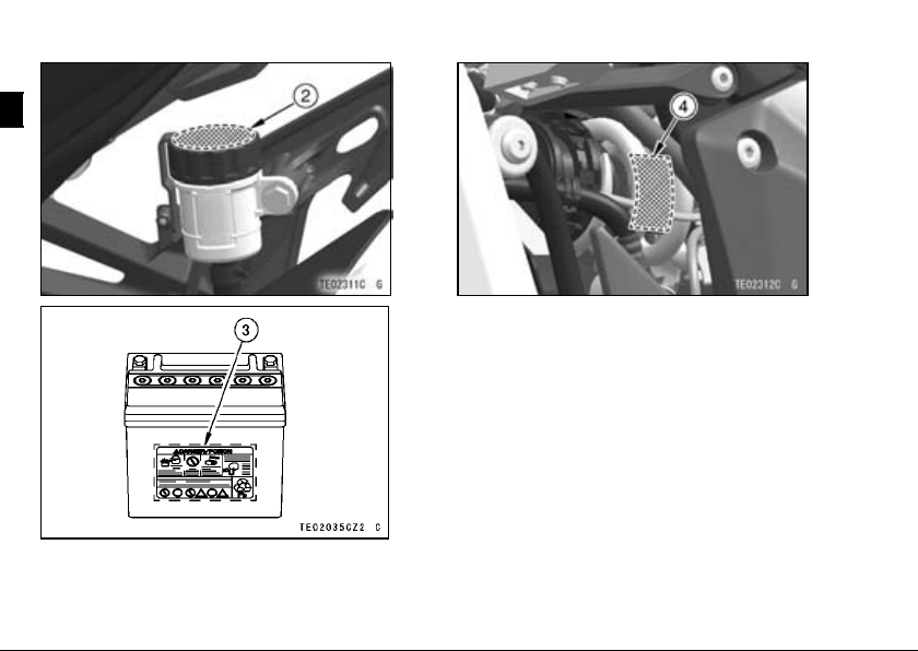
28 GENERAL INFORMATION
2. Brake Fluid (Rear)
3. Battery Poison/Danger
4. Rear Shock Ab sorb er Warning
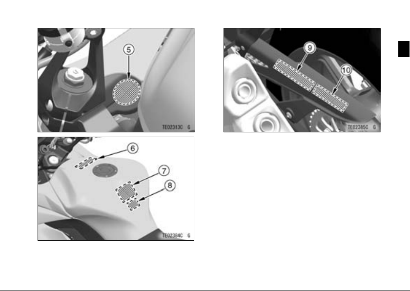
GENERAL INFORMATION 29
5. Radiator Cap Danger
*6. Helmet Wearing
7. Fuel Notice
**8. Fuel Level
9. Important Drive Chain Information
10. Tire and Load Dat a
*: only on Thailand model
**: only on Sou th east Asia B1 model

30 GENERAL INFORMATION
11. Windshield Warning
***12. Vacuum Ho se Routing Diagram
****13. Vehicle Emission Control Information
*****14. Stationary Noise Test Information
***: only on Southeast Asia B1 and
Thailand models
****: only on Philippines model
*****: only on Australia model

****** 15. Stationary Noise Test Information
******: only on Southeast Asia B2 and
Thailand models
GENERAL INFORMATION 31

32 GENERAL INFORMATION
1)
2)
3)

4) 5)
6) only on Thailand model
GENERAL INFORMATION 33

34 GENERAL INFORMATION
7)
 only on Southeast Asia B1 model
9)
10)

GENERAL INFORMATION 35
11) 12) only on Southeast Asia B1 and
Thailand models

36 GENERAL INFORMATION
13) only on Philippines m odel
14) only on Australia model
15) only on Southeast Asia B2 and
Thailand models

Location of Parts
GENERAL INFORMATION 37
1. Rear View Mirrors
2. Clutch Lever
3. Starter Lockout Switch
4. Meter Instrument
5. Brake Fluid Reservoir (Front)
6. Front Brake Lever
7. Throttle Grip
8. Left Handlebar Switches
9. Rebound Damping Force Adjusters
10. Spring Preload Adjusters
11. Ignition Switch/Steering Lock
12. Windshield Adjuster Knob
13. Right Handlebar Switches

38 GENERAL INFORMATION
1. Headlight
2. Spark Plugs
3. Fuel Tank
4. Battery
5. Helmet Cables
(Southeast Asia B2
model only)
6. Tool Kit
7. Seat Lock
8. Turn Signal Lights
9. License Plate Light
10. Front Fork
11. Radi ato r
12. Side Stand S w itch
13. Shift Pedal
14. Side Stand
15. Coolant Reserve Tank
16. Swingarm
17. Drive Chain
18. Chain Adjuster
19. Muffler
20. Tying Ho ok

GENERAL INFORMATION 39
1. Tail/Brake Light
2. Passenger’s Seat
3. Spring Preload Adjuster
4. Rider’s Seat
5. Rear Shock Absorber
6. Fuse Bo x
7. Fuel Tank Cap
8. Air Cleaner
9. Muffler
10. Brake Discs
11. Brake Calipers
12. Brake Fluid Reservoir (Rear)
13. Rebound Damping Force Adjuster
14. Rear Brake Light Switch
15. Rear Brake Pedal
16. Oil Level Inspection Window
17. Idle Adjusting Screw
18. Compression Damping Force
Adjuster

40 GENERAL INFORMATION
Meter Instruments
1. Tachometer
2. MODE Button
3. RESET Button
4. Multifunction Meter
5. Fuel Gauge
6. Power Mode Indicator
7. Multifunction Display
-Odometer
— Trip Meter A/B
— Current/Average Mileage/Cruising Range
8. Economical Riding Indicator
9. Coolant Temperature M eter/Clock
10. KTRC Mode Indicator
11. Speedo meter
When the ignition switch is turned on, all LCD
functions are shown for a few seconds, then the
multifunction meter turns to operational mode.

Indicators
1. Left Turn Signal Indicator (Green)
Engine Warning Indicator (Yellow)
2.
3.
KTRC Indicator (Yellow)
High Beam Indicator (Blue)
4.
5.
Neutral Indicator (Green)
Right Turn Signal Indicator (Green)
6.
7.
Coolant Temperature Warning Indicator
8.
Oil Pressure Warning Indicator
Warning Indicator/Immobilizer Indicator
9.
(Red)
10.
11.
12.
13.
14.
Battery Warning Indicator
Immobilizer Warning Indicator
Fuel Level Warning Indicator
KTRC Warning Indicator
ABS Indicator (Yellow) (ABS model)
GENERAL INFORMATION 41

42 GENERAL INFORMATION
Indicator Initial Operation
When the ignition switch is turned on,
all indicators go on/off as shown in the
table. If any indicator does not operate
as shown, have it checked by an authorized Kawasaki dealer.
ON
□ □ □
□ □ ■
□ ■ ■
■ ■ ■
ON: When ignition switch is turned on.
: After a few seconds
:Whenenginestarts.
□ : Goes on.
■ :Goesoff.
*:
goes off shorty after the
motorcycle starts moving.
Indicators

GENERAL INFORMATION 43
When Warning Indicators Go On
or Blink
When warning indicators appear, there could be a problem with vehicle function.
Follow actions in the table after stopping the vehicle in a safe place.
*: The numbers in this column corresponds to reference numbers on page 41.
*No.
2
9
7
Indi-
cators
ON
Blink
ON
Status
Actions
The DFI system has malfunctioned. Have it checked by
an authorized Kawasaki dealer.
If this indicator blinks while pushing the starter button, the
vehicle-down sensor has been tripped and the engine
cannot be started. Turn the ignition switch off and then
back on to start the engine.
These indicators go on whenever the coolant temperature
rises to about 115°C (239°F). Refer to the Coolant
Temperature Meter/Clock section for more information
and follow instructions in it.

44 GENERAL INFORMATION
*No.
9
8
9
10
9
11
Indi-
cators
ON
ON
Blink
Status
Actions
These indicators go on whenever the oil pressure is
dangerously low or the ignition switch is in the “ON”
position with the engine not running. If these indicators
go on when the engine speed is above idle, stop the
engine immediately and check the engi ne oil level. If
the amount of engine oil is insufficient, add engine oil.
If the o il level is good, have the engine checked by an
authorized Kawasaki dealer.
These indicators go on if the battery voltage is less than
11.0 V or more than 16.0 V. I f they go on, charge the
battery. If they still go on after charging the battery,
have the battery and/or charging system checked by an
authorized Kawasaki dealer.
The immobilizer system has malfunctioned. These
indicators blink if an improperly coded key is used or
if there is a miscommunication betwe en the antenna
and key. Have the immobilizer system checked by an
authorized Kawasaki dealer.

GENERAL INFORMATION 45
*No.
Indi-
cators
12
13 ON
14 ON
Status
Blink
Blink (including
all segments)
*1
Actions
The lowest segment and fuel level warning indicator
blink in the multifunction disp lay when approximately
4.2 L (1.1 US gal) of usable fuel remains. Refuel at the
earliest opportu nity. If the vehicle is on the side stand, the
warning indicator cannot estimate the amount of fuel in
the tank. Stand the vehicle upright to check the fuel level.
The fuel level warning system has malfunctioned. Have
the fuel level warning system checked by an authorized
Kawasaki dealer.
The KTRC system is not working and the KTRC and
Power mode indicators
*2
blink. Have the system checked
by an authorized Kawasaki dealer.
The ABS has malfunctioned. ABS will not work but
conventional brakes function . Have the ABS checked by
an authorized Kawasaki dealer.

46 GENERAL INFORMATION
*1:
ABS indicator may go on:
After continuous riding on a rough road.
○
When the engine is started with the stand raised and the transmission engaged,
○
and the rear wheel turns.
When accelerating so abruptly that the front wheel leaves the ground.
○
When the ABS has been subjected to strong electrical inte rference.
○
When tire pressure is abnormal. Adjust tire pressure.
○
When a tire different in size from the standard size is being used. Replace with
○
standard size.
When the wheel is d eformed. Replace the wheel.
○
If this happens, first turn the ignition switch off, and then back on, and ride the
motorcycle at 5 km/h (3.1 mph) or more. The ABS indicator should then go off. If it
does not, have the ABS checked by an authorized Kawasaki dealer.
*2:
Refer t o the Meter Instruments section for indicator position.

Other Indicators
Indicators
*No.
1
3
4
5
6
9
GENERAL INFORMATION 47
Status
When th e turn signal switch is pushed to the left, this indicator blinks.
When the KTRC functions, this in dicator goes o n.
When the headlight is on high beam, this indicator goes on.
When the transmission is in neutral, this ind icator goes on.
When th e turn signal switch is pushed to the right, this indica tor blinks.
When the ignition switch is turned off, this indicator will start blinking*1,
which indicates that the immobilizer system is functioning. After 24
hours, the red warning indicator/immobilizer ind icator will stop blinking.
However, the immobilizer system is still functioning.

48 GENERAL INFORMATION
*1: The red warning indicator/immobilizer indicator blinking mode can be set to either
on or off.
To stop the red warning indicator/immobilizer indicator bl inki ng, turn the ignition
○
switch off and then, within twenty seconds, push and hold the MODE a nd
RESET buttons simultaneously for more than two seconds.
When the battery is connected, red warning indicator/imm obilizer indicator
○
defaults to blinking mode.
When the battery voltage is l ow (below 12 V), the red warning
○
indicator/immobilizer indicator automatically stops blinking to prevent excessive
battery discharge.

Speedometer/Tachometer
A. Speedometer
B. Tachometer
C. Red Zone
GENERAL INFORMATION 49
the unit setting (km/h or mph) is correctly displayed before riding.
Refer to the Unit Setting in the Dis-
play Setting section.
Tachometer
The tachometer shows the engine
speed in revolutions per m inute (r/min,
rpm).
NOTICE
Engine speed should not be al-
lowed to enter the red zone; op-
eration in the red zone will over-
stress the engine and may cause
serious engine damage.
Speedometer
The speedometer is digital and can
be set for km/h or mph.
The unit setting can be changed ac-
cording to local regulations. Make sure
When the ignition switch is turned
on, the tachometer needle momentarily goes from the minimum to the
maximum reading, then back the minimum reading to check its operation.
If the tachometer does not operate
 Loading…
If you are a proud owner of a Kawasaki Ninja 1000 ABS or Z1000SX ABS 2015, then you know the importance of having the correct owner’s manual. It is an essential tool that helps you maintain your bike and keep it in top condition. The Kawasaki Ninja 1000 ABS Z1000SX ABS 2015 Owner’s Manual is a comprehensive document that covers everything you need to know about your bike.
This manual contains detailed information on safety, controls, maintenance, and troubleshooting. It also includes a detailed guide on how to use the instrument panel and how to perform routine maintenance tasks such as oil changes, tire pressures, and brake adjustments. With the Kawasaki Ninja 1000 ABS Z1000SX ABS 2015 Owner’s Manual, you can be confident that your bike is always in excellent condition.
So, if you want to make sure that your Kawasaki Ninja 1000 ABS or Z1000SX ABS 2015 is running smoothly, then you need to get your hands on this owner’s manual. It is an invaluable resource that will help you keep your bike in top condition and ensure that you are getting the most out of your riding experience.
In conclusion, the Kawasaki Ninja 1000 ABS Z1000SX ABS 2015 Owner’s Manual is a must-have for any owner of these fantastic bikes. It is a comprehensive guide that covers everything you need to know about your bike and will help you keep it in top condition for years to come. So, don’t wait any longer, get your copy today!
Language: English
Format: PDF
Kawasaki Ninja 1000 ABS Z1000SX ABS 2015 Owner’s Manual
![]()
Z1000SX
Z1000SX ABS
Ninja 1000
Ninja 1000 ABS
Motorcycle
Service Manual

Quick Reference Guide
This quick reference guide will assist you in locating a desired topic or procedure.
•Bend the pages back to match the black tab of the desired chapter number with the black tab on the edge at each table of contents page.
•Refer to the sectional table of contents for the exact pages to locate the specific topic required.
|
General Information |
1 |
j |
|
Periodic Maintenance |
2 |
j |
|
Fuel System (DFI) |
3 |
j |
|
Cooling System |
4 |
j |
|
Engine Top End |
5 |
j |
|
Clutch |
6 |
j |
|
Engine Lubrication System |
7 |
j |
|
Engine Removal/Installation |
8 |
j |
|
Crankshaft/Transmission |
9 |
j |
|
Wheels/Tires |
10 |
j |
|
Final Drive |
11 |
j |
|
Brakes |
12 |
j |
|
Suspension |
13 |
j |
|
Steering |
14 |
j |
|
Frame |
15 |
j |
|
Electrical System |
16 |
j |
|
Appendix |
17 |
j |

Z1000SX
Z1000SX ABS
Ninja 1000
Ninja 1000 ABS
Motorcycle
Service Manual
All rights reserved. No parts of this publication may be reproduced, stored in a retrieval system, or transmitted in any form or by any means, electronic mechanical photocopying, recording or otherwise, without the prior written permission of Quality Assurance Division/Motorcycle & Engine Company/Kawasaki Heavy Industries, Ltd., Japan.
No liability can be accepted for any inaccuracies or omissions in this publication, although every possible care has been taken to make it as complete and accurate as possible.
The right is reserved to make changes at any time without prior notice and without incurring an obligation to make such changes to products manufactured previously. See your Motorcycle dealer for the latest information on product improvements incorporated after this publication.
All information contained in this publication is based on the latest product information available at the time of publication. Illustrations and photographs in this publication are intended for reference use only and may not depict actual model component parts.
|
© 2010 Kawasaki Heavy Industries, Ltd. |
2nd Edition (0) : Jun. 20, 2011 |

LIST OF ABBREVIATIONS
|
A |
ampere(s) |
lb |
pound(s) |
|
ABDC |
after bottom dead center |
m |
meter(s) |
|
AC |
alternating current |
min |
minute(s) |
|
ATDC |
after top dead center |
N |
newton(s) |
|
BBDC |
before bottom dead center |
Pa |
pascal(s) |
|
BDC |
bottom dead center |
PS |
horsepower |
|
BTDC |
before top dead center |
psi |
pound(s) per square inch |
|
°C |
degree(s) Celsius |
r |
revolution |
|
DC |
direct current |
rpm |
revolution(s) per minute |
|
F |
farad(s) |
TDC |
top dead center |
|
°F |
degree(s) Fahrenheit |
TIR |
total indicator reading |
|
ft |
foot, feet |
V |
volt(s) |
|
g |
gram(s) |
W |
watt(s) |
|
h |
hour(s) |
Ω |
ohm(s) |
|
L |
liter(s) |
COUNTRY AND AREA CODES
|
AT |
Austria |
|
AU |
Australia |
|
BR |
Brazil |
|
CA |
Canada |
|
CAL |
California |
|
CH |
Switzerland |
|
DE |
Germany |
|
GB |
United Kingdom |
|
SEA-B1 |
Southeast Asia B1 (with Evaporative |
|
Emission Control System) |
|
|
SEA-B2 |
Southeast Asia B2 |
|
US |
United States |
|
WVTA |
WVTA Model with Honeycomb |
|
(FULL H) |
Catalytic Converter (Full Power) |
|
GB WVTA |
WVTA Model with Honeycomb Catalytic |
|
(FULL H) |
Converter (Left Side Traffic, Full Power) |
|
WVTA |
WVTA Model with Honeycomb |
|
(78.2 H) |
Catalytic Converter (78.2 Kw Power) |

EMISSION CONTROL INFORMATION
To protect the environment in which we all live, Kawasaki has incorporated crankcase emission (1) and exhaust emission (2) control systems in compliance with applicable regulations of the United States Environmental Protection Agency and California Air Resources Board. Additionally, Kawasaki has incorporated an evaporative emission control system (3) in compliance with applicable regulations of the California Air Resources Board on vehicles sold in California only.
1. Crankcase Emission Control System
This system eliminates the release of crankcase vapors into the atmosphere. Instead, the vapors are routed through an oil separator to the intake side of the engine. While the engine is operating, the vapors are drawn into combustion chamber, where they are burned along with the fuel and air supplied by the fuel injection system.
2. Exhaust Emission Control System
This system reduces the amount of pollutants discharged into the atmosphere by the exhaust of this motorcycle. The fuel, ignition, and exhaust systems of this motorcycle have been carefully designed and constructed to ensure an efficient engine with low exhaust pollutant levels.
The exhaust system of this model motorcycle manufactured primarily for sale in California includes a catalytic converter system.
3. Evaporative Emission Control System
Vapors caused by fuel evaporation in the fuel system are not vented into the atmosphere. Instead, fuel vapors are routed into the running engine to be burned, or stored in a canister when the engine is stopped. Liquid fuel is caught by a vapor separator and returned to the fuel tank.
The Clean Air Act, which is the Federal law covering motor vehicle pollution, contains what is commonly referred to as the Act’s “tampering provisions”.
“Sec. 203(a) The following acts and the causing thereof are prohibited.
(3)(A) for any person to remove or render inoperative any device or element of design installed on or in a motor vehicle or motor vehicle engine in compliance with regulations under this title prior to its sale and delivery to the ultimate purchaser, or for any manufacturer or dealer knowingly to remove or render inoperative any such device or element of design after such sale and delivery to the ultimate purchaser.
(3)(B) for any person engaged in the business of repairing, servicing, selling, leasing, or trading motor vehicles or motor vehicle engines, or who operates a fleet of motor vehicles knowingly to remove or render inoperative any device or element of design installed on or in a motor vehicle or motor vehicle engine in compliance with regulations under this title following its sale and delivery to the ultimate purchaser…”
NOTE
○The phrase “remove or render inoperative any device or element of design” has been generally interpreted as follows.
1.Tampering does not include the temporary removal or rendering inoperative of devices or elements of design in order to perform maintenance.
2.Tampering could include.
a.Maladjustment of vehicle components such that the emission standards are exceeded.
b.Use of replacement parts or accessories which adversely affect the performance or durability of the motorcycle.
c.Addition of components or accessories that result in the vehicle exceeding the standards.
d.Permanently removing, disconnecting, or rendering inoperative any component or element of design of the emission control systems.
WE RECOMMEND THAT ALL DEALERS OBSERVE THESE PROVISIONS OF FEDERAL LAW, THE VIOLATION OF WHICH IS PUNISHABLE BY CIVIL PENALTIES NOT EXCEEDING $10 000 PER VIOLATION.

TAMPERING WITH NOISE CONTROL SYSTEM PROHIBITED
Federal law prohibits the following acts or the causing thereof. (1) The removal or rendering inoperative by any person other than for purposes of maintenance, repair, or replacement, of any device or element of design incorporated into any new vehicle for the purpose of noise control prior to its sale or delivery to the ultimate purchaser or while it is in use, or (2) the use of the vehicle after such device or element of design has been removed or rendered inoperative by any person.
Among those acts presumed to constitute tampering are the acts listed below.
•Replacement of the original exhaust system or muffler with a component not in compliance with Federal regulations.
•Removal of the muffler(s) or any internal portion of the muffler(s).
•Removal of the air box or air box cover.
•Modifications to the muffler(s) or air intake system by cutting, drilling, or other means if such modifications result in increased noise levels.

Foreword
This manual is designed primarily for use by trained mechanics in a properly equipped shop. However, it contains enough detail and basic information to make it useful to the owner who desires to perform his own basic maintenance and repair work. A basic knowledge of mechanics, the proper use of tools, and workshop procedures must be understood in order to carry out maintenance and repair satisfactorily. Whenever the owner has insufficient experience or doubts his ability to do the work, all adjustments, maintenance, and repair should be carried out only by qualified mechanics.
In order to perform the work efficiently and to avoid costly mistakes, read the text, thoroughly familiarize yourself with the procedures before starting work, and then do the work carefully in a clean area. Whenever special tools or equipment are specified, do not use makeshift tools or equipment. Precision measurements can only be made if the proper instruments are used, and the use of substitute tools may adversely affect safe operation.
For the duration of the warranty period, we recommend that all repairs and scheduled maintenance be performed in accordance with this service manual. Any owner maintenance or repair procedure not performed in accordance with this manual may void the warranty.
To get the longest life out of your vehicle.
•Follow the Periodic Maintenance Chart in the Service Manual.
•Be alert for problems and non-scheduled maintenance.
•Use proper tools and genuine Kawasaki Motorcycle parts. Special tools, gauges, and testers that are necessary when servicing Kawasaki motorcycles are introduced by the Service Manual. Genuine parts provided as spare parts are listed in the Parts Catalog.
•Follow the procedures in this manual carefully. Don’t take shortcuts.
•Remember to keep complete records of maintenance and repair with dates and any new parts installed.
How to Use This Manual
In this manual, the product is divided into its major systems and these systems make up the manual’s chapters. The Quick Reference
Guide shows you all of the product’s system and assists in locating their chapters. Each chapter in turn has its own comprehensive Table of Contents.
For example, if you want ignition coil information, use the Quick Reference Guide to locate the Electrical System chapter. Then, use the Table of Contents on the first page of the chapter to find the Ignition Coil section.
Whenever you see symbols, heed their instructions! Always follow safe operating and maintenance practices.

 DANGER
DANGER indicates a hazardous situation which, if not avoided, will result in death or serious injury.
 WARNING
WARNING indicates a hazardous situation which, if not avoided, could result in death or serious injury.
NOTICE
NOTICE is used to address practices not related to personal injury.
This manual contains four more symbols which will help you distinguish different types of information.
NOTE
○This note symbol indicates points of particular interest for more efficient and convenient operation.
•Indicatesdone. a procedural step or work to be ○Indicates a procedural sub-step or how to do the work of the procedural step it follows. It
also precedes the text of a NOTE.
 Indicates a conditional step or what action to take based on the results of the test or inspection in the procedural step or sub-step it follows.
In most chapters an exploded view illustration of the system components follows the Table of Contents. In these illustrations you will find the instructions indicating which parts require specified tightening torque, oil, grease or a locking agent during assembly.
![]()
GENERAL INFORMATION 1-1
General Information |
|
|
Table of Contents |
|
|
1 |
|
|
Before Servicing ……………………………………………………………………………………………………… |
1-2 |
|
Model Identification………………………………………………………………………………………………….. |
1-7 |
|
General Specifications……………………………………………………………………………………………… |
1-10 |
|
Unit Conversion Table ……………………………………………………………………………………………… |
1-13 |
1-2 GENERAL INFORMATION
Before Servicing
Before starting to perform an inspection service or carry out a disassembly and reassembly operation on a motorcycle, read the precautions given below. To facilitate actual operations, notes, illustrations, photographs, cautions, and detailed descriptions have been included in each chapter wherever necessary. This section explains the items that require particular attention during the removal and reinstallation or disassembly and reassembly of general parts.
Especially note the following.
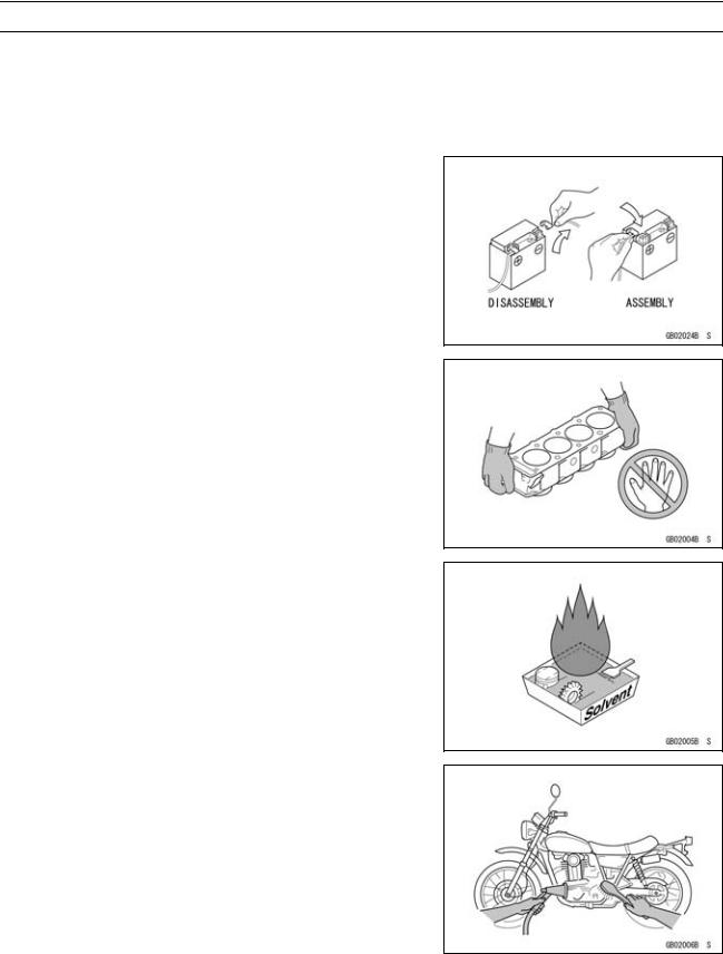
Battery Ground
Before completing any service on the motorcycle, disconnect the battery cables from the battery to prevent the engine from accidentally turning over. Disconnect the ground cable (–) first and then the positive (+). When completed with the service, first connect the positive (+) cable to the positive (+) terminal of the battery then the negative (–) cable to the negative terminal.
Edges of Parts
Lift large or heavy parts wearing gloves to prevent injury from possible sharp edges on the parts.
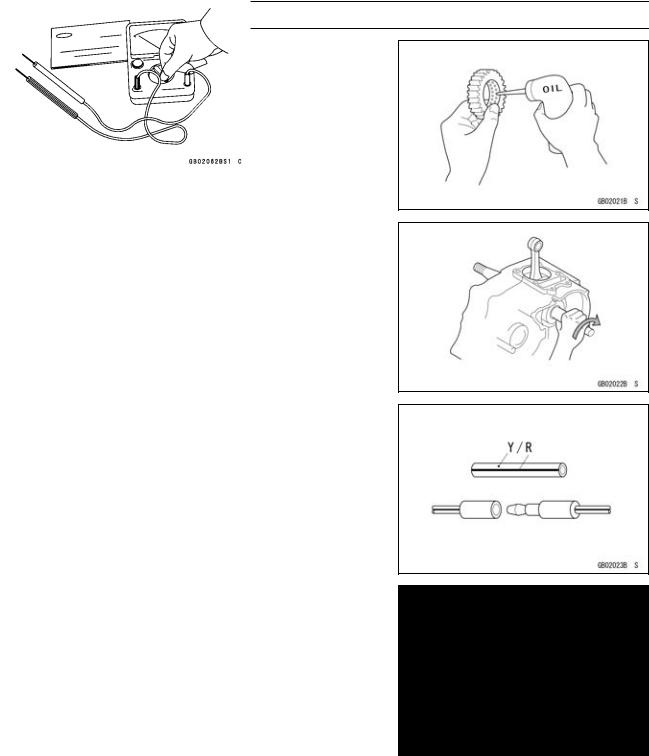
Solvent
Use a high-flush point solvent when cleaning parts. High -flush point solvent should be used according to directions of the solvent manufacturer.
Cleaning Vehicle before Disassembly
Clean the vehicle thoroughly before disassembly. Dirt or other foreign materials entering into sealed areas during vehicle disassembly can cause excessive wear and decrease performance of the vehicle.

GENERAL INFORMATION 1-3
Before Servicing
Arrangement and Cleaning of Removed Parts
Disassembled parts are easy to confuse. Arrange the parts according to the order the parts were disassembled and clean the parts in order prior to assembly.
Storage of Removed Parts
After all the parts including subassembly parts have been cleaned, store the parts in a clean area. Put a clean cloth or plastic sheet over the parts to protect from any foreign materials that may collect before re-assembly.
Inspection
Reuse of worn or damaged parts may lead to serious accident. Visually inspect removed parts for corrosion, discoloration, or other damage. Refer to the appropriate sections of this manual for service limits on individual parts. Replace the parts if any damage has been found or if the part is beyond its service limit.
Replacement Parts
Replacement parts must be KAWASAKI genuine or recommended by KAWASAKI. Gaskets, O-rings, oil seals, grease seals, circlips, cotter pins or self-locking nuts must be replaced with new ones whenever disassembled.
Assembly Order
In most cases assembly order is the reverse of disassembly, however, if assembly order is provided in this Service Manual, follow the procedures given.

1-4 GENERAL INFORMATION
Before Servicing
Tightening Sequence
Generally, when installing a part with several bolts, nuts, or screws, start them all in their holes and tighten them to a snug fit. Then tighten them according to the specified sequence to prevent case warpage or deformation which can lead to malfunction. Conversely when loosening the bolts, nuts, or screws, first loosen all of them by about a quarter turn and then remove them. If the specified tightening sequence is not indicated, tighten the fasteners alternating diagonally.
Tightening Torque
Incorrect torque applied to a bolt, nut, or screw may lead to serious damage. Tighten fasteners to the specified torque using a good quality torque wrench.
Force
Use common sense during disassembly and assembly, excessive force can cause expensive or hard to repair damage. When necessary, remove screws that have a non -permanent locking agent applied using an impact driver. Use a plastic-faced mallet whenever tapping is necessary.
Gasket, O-ring
Hardening, shrinkage, or damage of both gaskets and O-rings after disassembly can reduce sealing performance. Remove old gaskets and clean the sealing surfaces thoroughly so that no gasket material or other material remains. Install the new gaskets and replace the used O-rings when re-assembling.
Liquid Gasket, Non-permanent Locking Agent
For applications that require Liquid Gasket or a Non-permanent Locking Agent, clean the surfaces so that no oil residue remains before applying liquid gasket or non-permanent locking agent. Do not apply them excessively. Excessive application can clog oil passages and cause serious damage.

GENERAL INFORMATION 1-5
Before Servicing
Press
For items such as bearings or oil seals that must be pressed into place, apply small amount of oil to the contact area. Be sure to maintain proper alignment and use smooth movements when installing.
Ball Bearing and Needle Bearing
Do not remove pressed ball or needle unless removal is absolutely necessary. Replace with new ones whenever removed. Press bearings with the manufacturer and size marks facing out. Press the bearing into place by putting pressure on the correct bearing race as shown.
Pressing the incorrect race can cause pressure between the inner and outer race and result in bearing damage.
Oil Seal, Grease Seal
Do not remove pressed oil or grease seals unless removal is necessary. Replace with new ones whenever removed. Press new oil seals with manufacture and size marks facing out. Make sure the seal is aligned properly when installing.
Apply specified grease to the lip of seal before installing the seal.
Circlips, Cotter Pins
Replace the circlips or cotter pins that were removed with new ones. Take care not to open the clip excessively when installing to prevent deformation.
1-6 GENERAL INFORMATION
Before Servicing
Lubrication
It is important to lubricate rotating or sliding parts during assembly to minimize wear during initial operation. Lubrication points are called out throughout this manual, apply the specific oil or grease as specified.
Direction of Engine Rotation
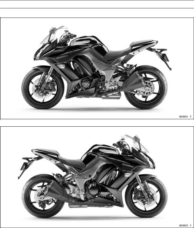
When rotating the crankshaft by hand, the free play amount of rotating direction will affect the adjustment. Rotate the crankshaft to positive direction (clockwise viewed from output side).
Electrical Wires
A two-color wire is identified first by the primary color and then the stripe color. Unless instructed otherwise, electrical wires must be connected to those of the same color.
Instrument
Use a meter that has enough accuracy for an accurate measurement. Read the manufacture’s instructions thoroughly before using the meter. Incorrect values may lead to improper adjustments.

GENERAL INFORMATION 1-7
Model Identification
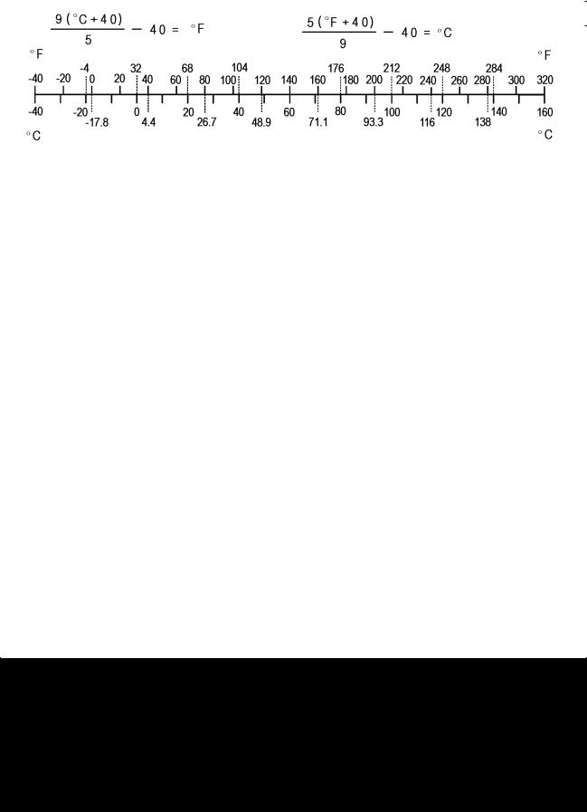
ZX1000GB (United States and Canada) Left Side View
ZX1000GB (United States and Canada) Right Side View
|
Frame Number |
Engine Number |
|
1-8 GENERAL INFORMATION
Model Identification
ZX1000GB (Europe) Left Side View
ZX1000GB (Europe) Right Side View

GENERAL INFORMATION 1-9
Model Identification
ZX1000HB Left Side View
ZX1000HB Right Side View

1-10 GENERAL INFORMATION
General Specifications
|
Items |
ZX1000GB GC/HB HC |
|
Dimensions |
|
|
Overall Length |
2 105 mm (82.87 in.) |
|
Overall Width |
790 mm (31.1 in.) |
|
Overall Height/High Position |
1 170 mm (40.06 in.)/1 230 mm (48.43 in.) |
|
Wheelbase |
1 445 mm (56.89 in.) |
|
Road Clearance |
135 mm (5.31 in.) |
|
Seat Height |
820 mm (32.28 in.) |
|
Curb Mass: |
|
|
ZX1000G |
228 kg (503 lb) |
|
ZX1000H |
231 kg (509 lb) |
|
Front: |
|
|
ZX1000G |
117 kg (258 lb) |
|
ZX1000H |
118 kg (260 lb) |
|
Rear: |
|
|
ZX1000G |
111 kg (245 lb) |
|
ZX1000H |
113 kg (249 lb) |
|
Fuel Tank Capacity |
19 L (5.0 US gal.) |
|
Performance |
|
|
Minimum Turning Radius |
3.1 m (10.1 ft) |
|
Engine |
|
|
Type |
4-stroke, DOHC, 4-cylinder |
|
Cooling System |
Liquid-cooled |
|
Bore and Stroke |
77.0 × 56.0 mm (3.03 × 2.20 in.) |
|
Displacement |
1 043 cm³ (63.64 cu in.) |
|
Compression Ratio |
11.8 : 1 |
|
Maximum Horsepower |
101.5 kW (138 PS) @9 600 r/min (rpm) |
|
(SEA-B1/B2) 100 kW (136 PS) @9 000 r/min (rpm) |
|
|
(WVTA (78.2 H)) 78.2 kW (106 PS) @9 100 r/min (rpm) |
|
|
(CA, US) – – – |
|
|
Maximum Torque |
110 N·m (11.2 kgf·m, 81.1 ft·lb) @7 800 r/min (rpm) |
|
(WVTA (78.2 H)) 95 N·m (9.7 kgf·m, 70 ft·lb) @7 500 r/min (rpm) |
|
|
(CA, US) – – – |
|
|
Carburetion System |
FI (Fuel Injection) KEIHIN TTK38 × 4 |
|
Starting System |
Electric starter |
|
Ignition System |
Battery and coil (transistorized) |
|
Timing Advance |
Electronically advanced (digital igniter) |
|
Ignition Timing |
From 10° BTDC @1 100 r/min (rpm) to 40.2° BTDC |
|
@5 200 r/min (rpm) |
|
|
Spark Plug |
NGK CR9EIA-9 |
|
Cylinder Numbering Method |
Left to right, 1-2-3-4 |
|
Firing Order |
1-2-4-3 |
|
Valve Timing: |
|
|
Intake: |
|
|
Open |
31° BTDC |
|
Close |
65° ABDC |
|
GENERAL INFORMATION 1-11 |
|
|
General Specifications |
|
|
Items |
ZX1000GB GC/HB HC |
|
Duration |
276° |
|
Exhaust: |
|
|
Open |
58° BBDC |
|
Close |
18° ATDC |
|
Duration |
256° |
|
Lubrication System |
Forced lubrication (wet sump) |
|
Engine Oil: |
|
|
Type |
API SG, SH, SJ, SL or SM with JASO MA, MA1 or MA2 |
|
Viscosity |
SAE 10W-40 |
|
Capacity |
4.0 L (4.2 US qt) |
|
Drive Train |
|
|
Primary Reduction System: |
|
|
Type |
Gear |
|
Reduction Ratio |
1.627 (83/51) |
|
Clutch Type |
Wet multi disc |
|
Transmission: |
|
|
Type |
6-speed, constant mesh, return shift |
|
Gear Ratios: |
|
|
1st |
2.600 (39/15) |
|
2nd |
1.950 (39/20) |
|
3rd |
1.600 (24/15) |
|
4th |
1.389 (25/18) |
|
5th |
1.238 (26/21) |
|
6th |
1.136 (25/22) |
|
Final Drive System: |
|
|
Type |
Chain drive |
|
Reduction Ratio |
2.733 (41/15) |
|
Overall Drive Ratio |
5.055 @Top gear |
|
Frame |
|
|
Type |
Tubular, diamond |
|
Caster (Rake Angle) |
24.5° |
|
Trail |
102 mm (4.02 in.) |
|
Front Tire: |
|
|
Type |
Tubeless |
|
Size |
120/70 ZR17 M/C (58W) |
|
Rim Size |
J17M/C × MT3.50 |
|
Rear Tire: |
|
|
Type |
Tubeless |
|
Size |
190/50 ZR17 M/C (73W) |
|
Rim Size |
J17M/C × MT6.00 |
|
Front Suspension: |
|
|
Type |
Telescopic fork (upside-down) |
|
Wheel Travel |
120 mm (4.72 in.) |

1-12 GENERAL INFORMATION
General Specifications
|
Items |
ZX1000GB GC/HB HC |
|
Rear Suspension: |
|
|
Type |
Swingarm |
|
Wheel Travel |
138 mm (5.43 in.) |
|
Brake Type: |
|
|
Front |
Dual discs |
|
Rear |
Single disc |
|
Electrical Equipment |
|
|
Battery |
12 V 8 Ah |
|
Headlight: |
|
|
Type |
Semi-sealed beam |
|
High Beam |
12 V 55 W |
|
Low Beam |
12 V 55 W |
|
Tail/Brake Light |
LED |
|
Alternator: |
|
|
Type |
Three-phase AC |
Specifications are subject to change without notice, and may not apply to every country.
GENERAL INFORMATION 1-13
Unit Conversion Table
|
Prefixes for Units: |
Units of Length: |
|
Prefix |
Symbol |
Power |
||
|
mega |
M |
× 1 000 |
000 |
|
|
kilo |
k |
× |
1 000 |
|
|
centi |
c |
× |
0.01 |
|
|
milli |
m |
× |
0.001 |
|
|
micro |
µ |
× 0.000001 |
Units of Mass:
|
kg |
× |
2.205 |
= |
lb |
|
g |
× |
0.03527 |
= |
oz |
Units of Volume:
|
L |
× |
0.2642 |
= |
gal (US) |
|
L |
× |
0.2200 |
= |
gal (IMP) |
|
L |
× |
1.057 |
= |
qt (US) |
|
L |
× |
0.8799 |
= |
qt (IMP) |
|
L |
× |
2.113 |
= |
pint (US) |
|
L |
× |
1.816 |
= |
pint (IMP) |
|
mL |
× |
0.03381 |
= |
oz (US) |
|
mL |
× |
0.02816 |
= |
oz (IMP) |
|
mL |
× |
0.06102 |
= |
cu in |
Units of Force:
|
N |
× |
0.1020 |
= |
kg |
|
N |
× |
0.2248 |
= |
lb |
|
kg |
× |
9.807 |
= |
N |
|
kg |
× |
2.205 |
= |
lb |
|
km |
× |
0.6214 |
= |
mile |
|
m |
× |
3.281 |
= |
ft |
|
mm |
× |
0.03937 |
= |
in |
Units of Torque:
|
N·m |
× |
0.1020 |
= |
kgf·m |
|
N·m |
× |
0.7376 |
= |
ft·lb |
|
N·m |
× |
8.851 |
= |
in·lb |
|
kgf·m |
× |
9.807 |
= |
N·m |
|
kgf·m |
× |
7.233 |
= |
ft·lb |
|
kgf·m |
× |
86.80 |
= |
in·lb |
Units of Pressure:
|
kPa |
× |
0.01020 |
= |
kgf/cm² |
|
kPa |
× |
0.1450 |
= |
psi |
|
kPa |
× |
0.7501 |
= |
cmHg |
|
kgf/cm² |
× |
98.07 |
= |
kPa |
|
kgf/cm² |
× |
14.22 |
= |
psi |
|
cmHg |
× |
1.333 |
= |
kPa |
Units of Speed:
km/h × 0.6214 = mph
Units of Power:
|
kW |
× |
1.360 |
= |
PS |
|
kW |
× |
1.341 |
= |
HP |
|
PS |
× |
0.7355 |
= |
kW |
|
PS |
× |
0.9863 |
= |
HP |
Units of Temperature:

PERIODIC MAINTENANCE 2-1
Periodic Maintenance
Table of Contents
|
Periodic Maintenance Chart ……………………………………………………………………………………… |
2-3 |
||
|
Torque and Locking Agent………………………………………………………………………………………… |
2-7 |
2 |
|
|
Specifications |
2-13 |
||
|
Special Tools ………………………………………………………………………………………………………….. |
2-15 |
||
|
Periodic Maintenance Procedures……………………………………………………………………………… |
2-17 |
||
|
Fuel System (DFI)…………………………………………………………………………………………………. |
2-17 |
||
|
Throttle Control System Inspection……………………………………………………………………….. |
2-17 |
||
|
Engine Vacuum Synchronization Inspection…………………………………………………………… |
2-17 |
||
|
Idle Speed Inspection …………………………………………………………………………………………. |
2-21 |
||
|
Idle Speed Adjustment………………………………………………………………………………………… |
2-22 |
||
|
Fuel Hose Inspection (fuel leak, damage, installation condition) ……………………………….. |
2-22 |
||
|
Evaporative Emission Control System (CAL and SEA-B1 Models) Inspection…………….. |
2-23 |
||
|
Cooling System…………………………………………………………………………………………………….. |
2-24 |
||
|
Coolant Level Inspection……………………………………………………………………………………… |
2-24 |
||
|
Radiator Hose and Pipe Inspection (coolant leak, damage, installation condition) ………. |
2-24 |
||
|
Engine Top End ……………………………………………………………………………………………………. |
2-24 |
||
|
Valve Clearance Inspection …………………………………………………………………………………. |
2-24 |
||
|
Valve Clearance Adjustment………………………………………………………………………………… |
2-26 |
||
|
Air Suction System Damage Inspection…………………………………………………………………. |
2-29 |
||
|
Clutch………………………………………………………………………………………………………………….. |
2-30 |
||
|
Clutch Operation Inspection…………………………………………………………………………………. |
2-30 |
||
|
Wheels/Tires………………………………………………………………………………………………………… |
2-31 |
||
|
Air Pressure Inspection……………………………………………………………………………………….. |
2-31 |
||
|
Wheel/Tire Damage Inspection…………………………………………………………………………….. |
2-31 |
||
|
Tire Tread Wear Inspection………………………………………………………………………………….. |
2-31 |
||
|
Wheel Bearing Damage Inspection ………………………………………………………………………. |
2-32 |
||
|
Final Drive……………………………………………………………………………………………………………. |
2-33 |
||
|
Drive Chain Lubrication Condition Inspection …………………………………………………………. |
2-33 |
||
|
Drive Chain Slack Inspection ……………………………………………………………………………….. |
2-33 |
||
|
Drive Chain Slack Adjustment ……………………………………………………………………………… |
2-34 |
||
|
Wheel Alignment Inspection ………………………………………………………………………………… |
2-34 |
||
|
Wheel Alignment Adjustment……………………………………………………………………………….. |
2-34 |
||
|
Drive Chain Wear Inspection ……………………………………………………………………………….. |
2-35 |
||
|
Chain Guide Wear Inspection ………………………………………………………………………………. |
2-35 |
||
|
Brakes…………………………………………………………………………………………………………………. |
2-36 |
||
|
Brake Fluid Leak (Brake Hose and Pipe) Inspection ……………………………………………….. |
2-36 |
||
|
Brake Hose and Pipe Damage and Installation Condition Inspection…………………………. |
2-37 |
||
|
Brake Operation Inspection …………………………………………………………………………………. |
2-37 |
||
|
Brake Fluid Level Inspection………………………………………………………………………………… |
2-37 |
||
|
Brake Pad Wear Inspection …………………………………………………………………………………. |
2-38 |
||
|
Brake Light Switch Operation Inspection ……………………………………………………………….. |
2-39 |
||
|
Suspension………………………………………………………………………………………………………….. |
2-40 |
||
|
Front Forks/Rear Shock Absorber Operation Inspection ………………………………………….. |
2-40 |
||
|
Front Fork Oil Leak Inspection……………………………………………………………………………… |
2-40 |
||
|
Rear Shock Absorber Oil Leak Inspection ……………………………………………………………… |
2-40 |
||
|
Rocker Arm Operation Inspection…………………………………………………………………………. |
2-40 |
||
|
Tie-Rod Operation Inspection ………………………………………………………………………………. |
2-41 |
||
|
Steering ………………………………………………………………………………………………………………. |
2-41 |
||
|
Steering Play Inspection ……………………………………………………………………………………… |
2-41 |
||
|
Steering Play Adjustment…………………………………………………………………………………….. |
2-41 |

2-2 PERIODIC MAINTENANCE
|
Steering Stem Bearing Lubrication ……………………………………………………………………….. |
2-43 |
|
Electrical System ………………………………………………………………………………………………….. |
2-44 |
|
Lights and Switches Operation Inspection……………………………………………………………… |
2-44 |
|
Headlight Aiming Inspection ………………………………………………………………………………… |
2-46 |
|
Sidestand Switch Operation Inspection …………………………………………………………………. |
2-47 |
|
Engine Stop Switch Operation Inspection………………………………………………………………. |
2-48 |
|
Others…………………………………………………………………………………………………………………. |
2-49 |
|
Chassis Parts Lubrication ……………………………………………………………………………………. |
2-49 |
|
Bolts, Nuts and Fasteners Tightness Inspection……………………………………………………… |
2-51 |
|
Replacement Parts ……………………………………………………………………………………………….. |
2-52 |
|
Air Cleaner Element Replacement………………………………………………………………………… |
2-52 |
|
Fuel Hose Replacement ……………………………………………………………………………………… |
2-52 |
|
Coolant Change …………………………………………………………………………………………………. |
2-54 |
|
Radiator Hose and O-ring Replacement………………………………………………………………… |
2-56 |
|
Engine Oil Change……………………………………………………………………………………………… |
2-57 |
|
Oil Filter Replacement ………………………………………………………………………………………… |
2-57 |
|
Brake Hose Replacement ……………………………………………………………………………………. |
2-58 |
|
Brake Fluid Change ……………………………………………………………………………………………. |
2-59 |
|
Master Cylinder Rubber Parts Replacement ………………………………………………………….. |
2-61 |
|
Caliper Rubber Parts Replacement ………………………………………………………………………. |
2-62 |
|
Spark Plug Replacement …………………………………………………………………………………….. |
2-66 |
PERIODIC MAINTENANCE 2-3
Periodic Maintenance Chart
The scheduled maintenance must be done in accordance with this chart to keep the motorcycle in good running condition.The initial maintenance is vitally important and must not be neglected.
Periodic Inspection
|
FREQUENCY |
Whichever |
* ODOMETER READING |
|||||||||||||
|
comes |
× 1 000 km |
See |
|||||||||||||
|
first |
(× 1 000 mile) |
||||||||||||||
|
Page |
|||||||||||||||
|
1 |
6 |
12 |
18 |
24 |
30 |
36 |
|||||||||
|
ITEM |
Every |
(0.6) |
(3.75) |
(7.5) |
(11.25) |
(15) |
(18.75) |
(22.5) |
|||||||
|
Fuel System |
|||||||||||||||
|
Throttle control system (play, |
year |
• |
• |
• |
• |
2-17 |
|||||||||
|
smooth return, no drag) — inspect |
|||||||||||||||
|
Engine vacuum synchronization — |
• |
• |
• |
2-17 |
|||||||||||
|
inspect |
|||||||||||||||
|
Idle speed — inspect |
• |
• |
• |
• |
2-21 |
||||||||||
|
Fuel leak (fuel hose and pipe) — |
year |
• |
• |
• |
• |
2-22 |
|||||||||
|
inspect |
|||||||||||||||
|
Fuel hose and pipe damage — |
year |
• |
• |
• |
• |
2-22 |
|||||||||
|
inspect |
|||||||||||||||
|
Fuel hose and pipe installation |
year |
• |
• |
• |
• |
2-22 |
|||||||||
|
condition — inspect |
|||||||||||||||
|
Evaporative emission control |
• |
• |
• |
• |
• |
• |
• |
2-23 |
|||||||
|
system function (CAL), (SEA-B1) |
|||||||||||||||
|
— inspect |
|||||||||||||||
|
Cooling System |
|||||||||||||||
|
Coolant level — inspect |
• |
• |
• |
• |
2-24 |
||||||||||
|
Coolant leak (water hose and |
year |
• |
• |
• |
• |
2-24 |
|||||||||
|
pipe) — inspect |
|||||||||||||||
|
Water hose damage — inspect |
year |
• |
• |
• |
• |
2-24 |
|||||||||
|
Water hose installation condition — |
year |
• |
• |
• |
• |
2-24 |
|||||||||
|
inspect |
|||||||||||||||
|
Engine Top End |
|||||||||||||||
|
US, CA, CAL |
• |
2-24 |
|||||||||||||
|
Model |
|||||||||||||||
|
Valve clearance — |
|||||||||||||||
|
Other than |
|||||||||||||||
|
inspect |
Every 42 000 km (26 250 mile) |
2-24 |
|||||||||||||
|
US, CA, CAL |
|||||||||||||||
|
Models |
|||||||||||||||
|
Air suction system damage — |
• |
• |
• |
2-29 |
|||||||||||
|
inspect |
|||||||||||||||
|
Clutch |
|||||||||||||||
|
Clutch operation (play, |
• |
• |
• |
• |
2-30 |
||||||||||
|
disengagement, engagement) — |
|||||||||||||||
|
inspect |
|||||||||||||||
|
Wheels and Tires |
|||||||||||||||
|
Tire air pressure — inspect |
year |
• |
• |
• |
2-31 |
||||||||||
|
Wheel/tire damage — inspect |
• |
• |
• |
2-31 |
|||||||||||
|
Tire tread wear, abnormal wear — |
• |
• |
• |
2-31 |
|||||||||||
|
inspect |
|||||||||||||||
|
Wheel bearing damage — inspect |
year |
• |
• |
• |
2-32 |

2-4 PERIODIC MAINTENANCE
Periodic Maintenance Chart
|
FREQUENCY |
Whichever |
* ODOMETER READING |
|||||||||||
|
comes |
× 1 000 km |
See |
|||||||||||
|
first |
(× 1 000 mile) |
||||||||||||
|
Page |
|||||||||||||
|
1 |
6 |
12 |
18 |
24 |
30 |
36 |
|||||||
|
ITEM |
Every |
(0.6) |
(3.75) |
(7.5) |
(11.25) |
(15) |
(18.75) |
(22.5) |
|||||
|
Final Drive |
|||||||||||||
|
Drive chain lubrication condition — |
Every 600 km (400 mile) |
2-33 |
|||||||||||
|
inspect # |
|||||||||||||
|
Drive chain slack — inspect # |
Every 1 000 km (600 mile) |
2-33 |
|||||||||||
|
Drive chain wear — inspect # |
• |
• |
• |
2-35 |
|||||||||
|
Drive chain guide wear — inspect |
• |
• |
• |
2-35 |
|||||||||
|
Brakes |
|||||||||||||
|
Brake fluid leak (brake hose and |
year |
• |
• |
• |
• |
• |
• |
• |
2-36 |
||||
|
pipe) — inspect |
|||||||||||||
|
Brake hose and pipe damage — |
year |
• |
• |
• |
• |
• |
• |
• |
2-37 |
||||
|
inspect |
|||||||||||||
|
Brake hose and pipe installation |
year |
• |
• |
• |
• |
• |
• |
• |
2-37 |
||||
|
condition — inspect |
|||||||||||||
|
Brake operation (effectiveness, |
year |
• |
• |
• |
• |
• |
• |
• |
2-37 |
||||
|
play, no drag) — inspect |
|||||||||||||
|
Brake fluid level — inspect |
6 |
• |
• |
• |
• |
• |
• |
• |
2-37 |
||||
|
months |
|||||||||||||
|
Brake pad wear — inspect # |
• |
• |
• |
• |
• |
• |
2-38 |
||||||
|
Brake light switch operation — |
• |
• |
• |
• |
• |
• |
• |
2-39 |
|||||
|
inspect |
|||||||||||||
|
Suspension |
|||||||||||||
|
Front forks/rear shock absorber |
• |
• |
• |
2-40 |
|||||||||
|
operation (damping and smooth |
|||||||||||||
|
stroke) — inspect |
|||||||||||||
|
Front forks/rear shock absorber |
year |
• |
• |
• |
2-40 |
||||||||
|
oil leak — inspect |
|||||||||||||
|
Rocker arm operation — inspect |
• |
• |
• |
2-40 |
|||||||||
|
Tie-rods operation — inspect |
• |
• |
• |
2-41 |
|||||||||
|
Steering |
|||||||||||||
|
Steering play — inspect |
year |
• |
• |
• |
• |
2-41 |
|||||||
|
Steering stem bearings — lubricate |
2 years |
• |
2-43 |
||||||||||
|
Electrical System |
|||||||||||||
|
Lights and switches operation — |
year |
• |
• |
• |
2-44 |
||||||||
|
inspect |
|||||||||||||
|
Headlight aiming — inspect |
year |
• |
• |
• |
2-46 |
||||||||
|
Sidestand switch operation — |
year |
• |
• |
• |
2-47 |
||||||||
|
inspect |
|||||||||||||
|
Engine stop switch operation — |
year |
• |
• |
• |
2-48 |
||||||||
|
inspect |
|||||||||||||
|
Others |
|||||||||||||
|
Chassis parts — lubricate |
year |
• |
• |
• |
2-49 |
||||||||
|
Bolts and nuts tightness — inspect |
• |
• |
• |
• |
2-51 |

PERIODIC MAINTENANCE 2-5
Periodic Maintenance Chart
#: Service more frequently when operating in severe conditions; dusty, wet, muddy, high speed or frequent starting/stopping.
*: For higher odometer readings, repeat at the frequency interval established here.
2-6 PERIODIC MAINTENANCE
Periodic Maintenance Chart
Periodic Replacement Parts
|
FREQUENCY |
Whichever |
* ODOMETER READING |
||||||||||
|
comes |
× 1 000 km |
See |
||||||||||
|
first |
(× 1 000 mile) |
|||||||||||
|
Page |
||||||||||||
|
1 |
12 |
24 |
36 |
48 |
||||||||
|
ITEM |
Every |
(0.6) |
(7.5) |
(15) |
(22.5) |
(30) |
||||||
|
Air cleaner element # — replace |
Every 18 000 km (11 250 mile) |
2-52 |
||||||||||
|
Fuel hose — replace |
5 years |
2-52 |
||||||||||
|
Coolant — change |
3 years |
• |
2-54 |
|||||||||
|
Radiator hose and O-ring — replace |
3 years |
• |
2-56 |
|||||||||
|
Engine oil # — change |
year |
• |
• |
• |
• |
• |
2-57 |
|||||
|
Oil filter — replace |
year |
• |
• |
• |
• |
• |
2-57 |
|||||
|
Brake hose — replace |
4 years |
• |
2-58 |
|||||||||
|
Brake fluid — change |
2 years |
• |
• |
2-59 |
||||||||
|
Rubber parts of master cylinder and caliper — |
4 years |
• |
2-61, |
|||||||||
|
replace |
2-62 |
|||||||||||
|
Spark plug — replace |
• |
• |
• |
• |
2-66 |
#: Service more frequently when operating in severe conditions; dusty, wet, muddy, high speed or frequent starting/stopping.
*: For higher odometer readings, repeat at the frequency interval established here.
![]()
PERIODIC MAINTENANCE 2-7
Torque and Locking Agent
The following tables list the tightening torque for the major fasteners requiring use of a non-permanent locking agent or silicone sealant etc.
Letters used in the “Remarks” column mean:
AL: Tighten the two clamp bolts alternately two times to ensure even tightening torque. G: Apply grease.
L: Apply a non-permanent locking agent. MO: Apply molybdenum disulfide oil solution.
(mixture of the engine oil and molybdenum disulfide grease in a weight ratio 10 : 1)
R:Replacement Parts
S:Follow the specified tightening sequence. Si: Apply silicone grease (ex. PBC grease).
SS: Apply silicone sealant.
|
Fastener |
Torque |
Remarks |
|||
|
N·m |
kgf·m |
ft·lb |
|||
|
Fuel System (DFI) |
|||||
|
Upper Air Cleaner Housing Screws |
1.1 |
0.11 |
9.7 in·lb |
||
|
Throttle Body Assy Holder Clamp Bolts |
2.9 |
0.30 |
26 in·lb |
||
|
Air Cleaner Duct Clamp Bolts |
2.0 |
0.20 |
18 in·lb |
||
|
Delivery Pipe Assy Mounting Screws |
3.4 |
0.35 |
30 in·lb |
||
|
Oxygen Sensor (Equipped Models) |
44 |
4.5 |
32 |
||
|
Intake Air Temperature Sensor Mounting Screw |
1.2 |
0.12 |
11 in·lb |
||
|
Water Temperature Sensor |
30 |
3.0 |
22 |
||
|
Exhaust Butterfly Valve Actuator Pulley Bolt |
5.0 |
0.51 |
44 in·lb |
||
|
Exhaust Butterfly Valve Actuator Mounting |
1.2 |
0.12 |
11 in·lb |
||
|
Screws |
|||||
|
Fuel Pump Bolts |
9.8 |
1.0 |
87 in·lb |
L |
|
|
Cooling System |
|||||
|
Hot Windshield Mounting Bolts |
9.8 |
1.0 |
87 in·lb |
||
|
Coolant By-pass Fitting Bolt |
8.8 |
0.90 |
78 in·lb |
L |
|
|
Thermostat Housing Bolts |
5.9 |
0.60 |
52 in·lb |
L |
|
|
Radiator (Water) Hose Clamp Screws |
2.9 |
0.30 |
26 in·lb |
||
|
Water Pipe Bolts |
12 |
1.2 |
106 in·lb |
L |
|
|
Water Pump Impeller Bolt |
9.8 |
1.0 |
87 in·lb |
||
|
Water Pump Cover Bolts |
11 |
1.1 |
97 in·lb |
||
|
Coolant Drain Bolt |
11 |
1.1 |
97 in·lb |
||
|
Engine Top End |
|||||
|
Air Suction Valve Cover Bolts |
9.8 |
1.0 |
87 in·lb |
L |
|
|
Spark Plugs |
13 |
1.3 |
115 in·lb |
||
|
Cylinder Head Cover Bolts |
9.8 |
1.0 |
87 in·lb |
S |
|
|
Hot Windshield Mounting Bolts |
9.8 |
1.0 |
87 in·lb |
||
|
Camshaft Sprocket Bolts |
15 |
1.5 |
11 |
L |
|
|
Front Camshaft Chain Guide Bolt (Upper) |
25 |
2.5 |
18 |
||
|
Rear Camshaft Chain Guide Bolt |
25 |
2.5 |
18 |
||
|
Front Camshaft Chain Guide Bolt (Lower) |
12 |
1.2 |
106 in·lb |
||
|
Throttle Body Assy Holder Bolts |
12 |
1.2 |
106 in·lb |
L |

2-8 PERIODIC MAINTENANCE
Torque and Locking Agent
|
Fastener |
Torque |
Remarks |
|||
|
N·m |
kgf·m |
ft·lb |
|||
|
Cylinder Head Bolts (M6) |
12 |
1.2 |
106 in·lb |
S |
|
|
Upper Camshaft Chain Guide Bolts |
12 |
1.2 |
106 in·lb |
S |
|
|
Plugs |
19.6 |
2.0 |
14 |
L |
|
|
Camshaft Cap Bolts |
12 |
1.2 |
106 in·lb |
S |
|
|
Cylinder Head Bolts (M10) (First) |
20 |
2.0 |
15 |
S, MO |
|
|
Cylinder Head Bolts (M10) (Final) |
54 |
5.5 |
40 |
S, MO |
|
|
Camshaft Chain Tensioner Mounting Bolts |
11 |
1.1 |
97 in·lb |
||
|
Camshaft Chain Tensioner Cap Bolt |
20 |
2.0 |
15 |
||
|
Exhaust Butterfly Valve Actuator Pulley Bolt |
5.0 |
0.51 |
44 in·lb |
||
|
Exhaust Butterfly Valve Actuator Bolts |
1.2 |
0.12 |
11 in·lb |
||
|
Muffler Body Mounting Bolts |
34 |
3.5 |
25 |
||
|
Premuffler Chamber Mounting Bolt |
34 |
3.5 |
25 |
||
|
Muffler Body Clamp Bolts |
21 |
2.1 |
15 |
||
|
Clutch |
|||||
|
Clutch Lever Assembly Clamp Bolts |
7.8 |
0.80 |
69 in·lb |
S |
|
|
Clutch Cover Bolts |
9.8 |
1.0 |
87 in·lb |
||
|
Oil Filler Plug |
2.0 |
0.20 |
18 in·lb |
||
|
Clutch Spring Bolts |
9.0 |
0.90 |
80 in·lb |
||
|
Clutch Hub Nut |
135 |
13.8 |
99.6 |
R |
|
|
Engine Lubrication System |
|||||
|
Oil Filler Plug |
2.0 |
0.20 |
18 in·lb |
||
|
Oil Cooler Bolts |
12 |
1.2 |
106 in·lb |
||
|
Oil Passage Plug |
20 |
2.0 |
15 |
L |
|
|
Radiator (Water) Hose Clamp Screws |
3.0 |
0.31 |
27 in·lb |
||
|
Oil Pressure Switch |
15 |
1.5 |
11 |
SS |
|
|
Oil Pressure Relief Valve |
15 |
1.5 |
11 |
L |
|
|
Oil Filter |
17 |
1.7 |
13 |
G, R |
|
|
Oil Filter Pipe |
25 |
2.5 |
18 |
L |
|
|
Oil Pan Bolts |
12 |
1.2 |
106 in·lb |
S |
|
|
Engine Oil Drain Bolt |
29 |
3.0 |
21 |
||
|
Engine Removal/Installation |
|||||
|
Upper Engine Bracket Bolts |
44 |
4.5 |
32 |
S |
|
|
Lower Engine Bracket Bolts |
59 |
6.0 |
44 |
S |
|
|
Upper Adjusting Collar |
9.8 |
1.0 |
87 in·lb |
S |
|
|
Upper Engine Mounting Bolt (L = 65) |
44 |
4.5 |
32 |
S |
|
|
Upper Adjusting Collar Locknut |
49 |
5.0 |
36 |
S |
|
|
Upper Engine Mounting Bolt (L = 40) |
44 |
4.5 |
32 |
S |
|
|
Lower Engine Mounting Nut |
44 |
4.5 |
32 |
S |
|
|
Lower Adjusting Collar Locknut |
49 |
5.0 |
36 |
S |
|
|
Middle Engine Bracket Bolts |
25 |
2.5 |
18 |
L, S |
|
|
Middle Engine Mounting Nut |
44 |
4.5 |
32 |
S |
|
|
Lower Adjusting Collar |
9.8 |
1.0 |
87 in·lb |
S |
|

PERIODIC MAINTENANCE 2-9
Torque and Locking Agent
|
Fastener |
Torque |
Remarks |
|||
|
N·m |
kgf·m |
ft·lb |
|||
|
Crankshaft/Transmission |
|||||
|
Balancer Shaft Clamp Bolt |
9.8 |
1.0 |
87 in·lb |
||
|
Balancer Shaft Lever Bolt |
25 |
2.5 |
18 |
L |
|
|
Breather Side Plate Bolt |
5.9 |
0.60 |
52 in·lb |
L |
|
|
Connecting Rod Big End Nuts |
see the text |
← |
← |
MO |
|
|
Breather Plate Bolts |
9.8 |
1.0 |
87 in·lb |
L |
|
|
Shift Drum Bearing Holder Bolts |
12 |
1.2 |
106 in·lb |
L |
|
|
Oil Passage Plugs |
20 |
2.0 |
15 |
L |
|
|
Oil Passage Plug |
9.8 |
1.0 |
87 in·lb |
||
|
Starter Motor Clutch Bolts |
12 |
1.2 |
106 in·lb |
L |
|
|
Crankcase Bolts (M7) |
20 |
2.0 |
15 |
S |
|
|
Crankcase Bolts (M9) |
42 |
4.2 |
31 |
S, MO |
|
|
Crankcase Bolts (M6) |
20 |
2.0 |
15 |
S |
|
|
Crankcase Bolts (M8) |
27 |
2.8 |
20 |
S |
|
|
Gear Positioning Lever Bolt |
12 |
1.2 |
106 in·lb |
||
|
Shift Drum Cam Bolt |
12 |
1.2 |
106 in·lb |
L |
|
|
Neutral Switch |
15 |
1.5 |
11 |
||
|
Shift Shaft Return Spring Pin |
39 |
4.0 |
29 |
L |
|
|
Shift Pedal Mounting Bolt |
25 |
2.5 |
18 |
||
|
Wheels/Tires |
|||||
|
Front Axle Clamp Bolt |
20 |
2.0 |
15 |
AL |
|
|
Front Axle |
108 |
11.0 |
79.7 |
||
|
Rear Axle Nut |
98 |
10 |
72 |
||
|
Final Drive |
|||||
|
Engine Sprocket Nut |
125 |
12.7 |
92.2 |
MO |
|
|
Drive Chain Guide Bolts |
9.8 |
1.0 |
87 in·lb |
||
|
Speed Sensor Mounting Bolt |
6.9 |
0.70 |
61 in·lb |
L |
|
|
Chain Adjuster Clamp Bolts |
64 |
6.5 |
47 |
||
|
Rear Sprocket Nuts |
59 |
6.0 |
44 |
||
|
Brakes |
|||||
|
Front Master Cylinder Reservoir Cap Stopper |
1.2 |
0.12 |
11 in·lb |
||
|
Screw |
|||||
|
Brake Lever Pivot Bolt |
1.0 |
0.10 |
8.8 in·lb |
Si |
|
|
Front Master Cylinder Bleed Valve |
5.4 |
0.55 |
48 in·lb |
||
|
Front Master Cylinder Clamp Bolts |
11 |
1.1 |
97 in·lb |
S |
|
|
Brake Lever Pivot Bolt Locknut |
5.9 |
0.60 |
52 in·lb |
||
|
Front Brake Light Switch Screw |
1.2 |
0.12 |
11 in·lb |
||
|
Brake Hose Banjo Bolts |
25 |
2.5 |
18 |
||
|
Front Caliper Assembly Bolts |
22 |
2.2 |
16 |
||
|
Front Caliper Mounting Bolts |
34 |
3.5 |
25 |
||
|
Bleed Valves |
7.8 |
0.80 |
69 in·lb |
||
|
Front Brake Pad Pins |
15 |
1.5 |
11 |
||
|
Front Brake Disc Mounting Bolts |
27 |
2.8 |
20 |
L |

2-10 PERIODIC MAINTENANCE
Torque and Locking Agent
|
Fastener |
Torque |
Remarks |
|||
|
N·m |
kgf·m |
ft·lb |
|||
|
Rear Master Cylinder Mounting Bolts |
25 |
2.5 |
18 |
||
|
Brake Pedal Bolt |
8.8 |
0.90 |
78 in·lb |
L |
|
|
Rear Master Cylinder Push Rod Locknut |
17 |
1.7 |
12 |
||
|
Rear Brake Disc Mounting Bolts |
27 |
2.8 |
20 |
L |
|
|
Rear Caliper Mounting Bolts |
25 |
2.5 |
18 |
||
|
Brake Pipe Joint Nuts |
18 |
1.8 |
13 |
||
|
Rear Brake Disc Mounting Bolts (ABS Equipped |
27 |
2.8 |
20 |
L |
|
|
Models) |
|||||
|
Suspension |
|||||
|
Upper Front Fork Clamp Bolts |
20 |
2.0 |
15 |
||
|
Lower Front Fork Clamp Bolts |
25 |
2.5 |
18 |
AL |
|
|
Piston Rod Nuts |
20 |
2.0 |
15 |
||
|
Front Fork Top Plugs |
34 |
3.5 |
25 |
||
|
Front Axle Clump Bolts |
20 |
2.0 |
15 |
AL |
|
|
Front Fork Bottom Allen Bolts |
35 |
3.6 |
26 |
||
|
Rear Shock Absorber Bolt (Upper) |
34 |
3.5 |
25 |
||
|
Tie-rod Nuts |
34 |
3.5 |
25 |
R |
|
|
Rear Shock Absorber Nut (Lower) |
34 |
3.5 |
25 |
R |
|
|
Rocker Arm Nut |
34 |
3.5 |
25 |
R |
|
|
Swingarm Pivot Adjusting Collar Locknut |
98 |
10 |
72 |
||
|
Swingarm Pivot Shaft Nut |
108 |
11.0 |
79.7 |
||
|
Torque Link Nuts |
|||||
|
34 |
3.5 |
25 |
|||
|
Steering |
|||||
|
Left Switch Housing Screws |
3.5 |
0.36 |
31 in·lb |
||
|
Upper Front Fork Clamp Bolts |
25 |
2.5 |
18 |
||
|
Handlebar Holder Bolts |
25 |
2.5 |
18 |
||
|
Handlebar Bolts |
34 |
3.5 |
25 |
L |
|
|
Right Switch Housing Screws |
3.5 |
0.36 |
31 in·lb |
||
|
Steering Stem Head Bolt |
108 |
11.0 |
79.7 |
||
|
Steering Stem Nut |
25 |
2.5 |
18 |
||
|
Lower Front Fork Clamp Bolts |
20 |
2.0 |
15 |
AL |
|
|
Frame |
|||||
|
Lower Fairing Upper Assembly Screws |
1.2 |
0.12 |
11 in·lb |
||
|
Lower Fairing Lower Assembly Screws |
1.2 |
0.12 |
11 in·lb |
||
|
Front Fender Mounting Bolts |
3.9 |
0.40 |
35 in·lb |
||
|
Stay Assembly Mounting Bolts |
6.9 |
0.70 |
61 in·lb |
||
|
Stopper Mounting Bolts |
4.2 |
0.42 |
37 in·lb |
L |
|
|
Rear Frame Bracket Bolts |
44 |
4.5 |
32 |
||
|
Front Footpeg Bracket Bolts |
25 |
2.5 |
18 |
||
|
Rear Footpeg Bracket Bolts |
25 |
2.5 |
18 |
||
|
Rear Frame Bolts |
25 |
2.5 |
18 |
L |
|
|
Sidestand Switch Bolt |
8.8 |
0.90 |
78 in·lb |
L |
|
|
Sidestand Bracket Bolts |
49 |
5.0 |
36 |
L |

PERIODIC MAINTENANCE 2-11
Torque and Locking Agent
|
Fastener |
Torque |
Remarks |
|||
|
N·m |
kgf·m |
ft·lb |
|||
|
Sidestand Bolt |
44 |
4.5 |
32 |
||
|
Grab Rail Mounting Bolts |
25 |
2.5 |
18 ft·lb |
||
|
Electrical System |
|||||
|
Switch Housing Screws |
3.5 |
0.36 |
31 in·lb |
||
|
Oxygen Sensor (Equipped Models) |
44 |
4.5 |
32 |
||
|
Front Brake Light Switch Screw |
1.2 |
0.12 |
11 in·lb |
||
|
Front Turn Signal Light Mounting Screws |
1.2 |
0.12 |
11 in·lb |
||
|
Licence Plate Light Mounting Screws |
1.2 |
0.12 |
11 in·lb |
||
|
Intake Air Temperature Sensor Mounting Screw |
1.2 |
0.12 |
11 in·ib |
||
|
Spark Plugs |
13 |
1.3 |
115 in·lb |
||
|
Crankshaft Sensor Cover Bolts |
12 |
1.2 |
106 in·lb |
||
|
Water Temperature Sensor |
30 |
3.0 |
22 |
||
|
Timing Rotor Bolt |
39 |
4.0 |
29 |
||
|
Crankshaft Sensor Bolts |
5.9 |
0.60 |
52 in·lb |
||
|
Starter Motor Cable Terminal Nut |
5.9 |
0.60 |
52 in·lb |
||
|
Starter Motor Terminal Locknut |
11 |
1.1 |
97 in·lb |
||
|
Starter Motor Mounting Bolts |
9.8 |
1.0 |
87 in·lb |
||
|
Alternator Rotor Bolt |
155 |
15.8 |
114 |
||
|
Stator Coil Bolts |
12 |
1.2 |
106 in·ib |
L |
|
|
Starter Motor Through Bolts |
4.9 |
0.50 |
43 in·lb |
||
|
Brush Holder Screw |
3.8 |
0.39 |
34 in·ib |
||
|
Oil Pressure Switch |
15 |
1.5 |
11 |
SS |
|
|
Oil Pressure Switch Terminal Bolt |
2.0 |
0.20 |
18 in·ib |
G |
|
|
Alternator Cover Bolts |
12 |
1.2 |
106 in·lb |
||
|
Alternator Lead Holding Plate Bolt |
12 |
1.2 |
106 in·ib |
L |
|
|
Neutral Switch |
15 |
1.5 |
11 |
||
|
Engine Ground Cable Terminal Bolt |
9.8 |
1.0 |
87 in·lb |
||
|
Sidestand Switch Bolt |
8.8 |
0.90 |
78 in·lb |
L |
|
|
Speed Sensor Mounting Bolt |
6.9 |
0.70 |
61 in·lb |
L |

2-12 PERIODIC MAINTENANCE
Torque and Locking Agent
The table below, relating tightening torque to thread diameter, lists the basic torque for the bolts and nuts. Use this table for only the bolts and nuts which do not require a specific torque value. All of the values are for use with dry solvent-cleaned threads.
Basic Torque for General Fasteners
|
Threads Diameter |
Torque |
||||||||
|
(mm) |
N·m |
kgf·m |
ft·lb |
||||||
|
5 |
3.4 |
4.9 |
0.35 |
0.50 |
30 |
43 in·lb |
|||
|
6 |
5.9 |
7.8 |
0.60 |
0.80 |
52 |
69 in·lb |
|||
|
8 |
14 |
19 |
1.4 |
1.9 |
10.0 |
13.5 |
|||
|
10 |
25 |
34 |
2.6 |
3.5 |
19.0 |
25 |
|||
|
12 |
44 |
61 |
4.5 |
6.2 |
33 |
45 |
|||
|
14 |
73 |
98 |
7.4 |
10.0 |
54 |
72 |
|||
|
16 |
115 |
155 |
11.5 |
16.0 |
83 |
115 |
|||
|
18 |
165 |
225 |
17.0 |
23.0 |
125 |
165 |
|||
|
20 |
225 |
325 |
23.0 |
33.0 |
165 |
240 |

PERIODIC MAINTENANCE 2-13
Specifications
|
Item |
Standard |
Service Limit |
||
|
Fuel System (DFI) |
||||
|
Throttle Grip Free Play |
2 3 mm (0.08 0.12 in.) |
– – – |
||
|
Idle Speed |
1 100 ±50 r/min (rpm) |
– – – |
||
|
Bypass Screws (Turn Out) |
2 1/2 (for reference) |
– – – |
||
|
Throttle Body Vacuum |
40.7 ±1.3 kPa (305 ±10 mmHg) at idle |
– – – |
||
|
speed |
||||
|
Air Cleaner Element |
Viscous paper element |
– – – |
||
|
Cooling System |
||||
|
Coolant: |
||||
|
Type (Recommended) |
Permanent type of antifreeze |
– – – |
||
|
Color |
Green |
– – – |
||
|
Mixed Ratio |
Soft water 50%, Coolant 50% |
– – – |
||
|
Freezing Point |
–35°C (–31°F) |
– – – |
||
|
Total Amount |
2.9 L (3.1 US qt) |
– – – |
||
|
Engine Top End |
||||
|
Valve Clearance: |
||||
|
Exhaust |
0.22 |
0.31 mm (0.0087 |
0.0122 in.) |
– – – |
|
Intake |
0.15 |
0.24 mm (0.0059 |
0.0094 in.) |
– – – |
|
Clutch |
||||
|
Clutch Lever Free Play |
2 3 mm (0.08 0.12 in.) |
– – – |
||
|
Engine Lubrication System |
||||
|
Engine Oil: |
||||
|
Type |
API SG, SH, SJ, SL or SM with JASO |
– – – |
||
|
MA, MA1 or MA2 |
||||
|
Viscosity |
SAE 10W-40 |
– – – |
||
|
Capacity |
3.2 L (3.4 US qt) (when filter is not |
– – – |
||
|
removed) |
||||
|
3.8 L (4.0 US qt) (when filter is removed) |
– – – |
|||
|
4.0 L (4.2 US qt) (when engine is |
– – – |
|||
|
completely dry) |
||||
|
Wheels/Tires |
||||
|
Tread Depth: |
||||
|
Front |
3.6 mm (0.14 in.) |
1 mm (0.04 in.), |
||
|
(AT, CH, DE) |
||||
|
1.6 mm (0.06 in.) |
||||
|
Rear |
5.3 mm (0.21 in.) |
Up to 130 km/h (80 mph): |
||
|
2 mm (0.08 in.), |
||||
|
Over 130 km/h (80 mph): |
||||
|
3 mm (0.12 in.) |
||||
|
Air Pressure (when Cold): |
||||
|
Front |
Up to 180 kg (397 lb) load: |
– – – |
||
|
250 kPa (2.5 kgf/cm², 36 psi) |
||||
|
Rear |
Up to 180 kg (397 lb) load: |
– – – |
||
|
290 kPa (2.9 kgf/cm², 42 psi) |
||||
|
Final Drive |
||||
|
Drive Chain Slack |
20 30 mm (0.8 1.2 in.) |
– – – |

2-14 PERIODIC MAINTENANCE
Specifications
|
Item |
Standard |
Service Limit |
|
Drive Chain Wear (20-link |
317.5 318.2 mm (12.50 12.53 in.) |
319 mm (12.56 in.) |
|
Length) |
||
|
Standard Chain: |
||
|
Make |
ENUMA |
– – – |
|
Type |
EK525ZX |
– – – |
|
Link |
112 Links |
– – – |
|
Brakes |
||
|
Brake Fluid: |
||
|
Grade |
DOT4 |
– – – |
|
Brake Pad Lining |
||
|
Thickness: |
||
|
Front |
4.0 mm (0.16 in.) |
1 mm (0.04 in.) |
|
Rear |
5.0 mm (0.20 in.) |
1 mm (0.04 in.) |
|
Brake Light Timing: |
||
|
Front |
Pulled ON |
– – – |
|
Rear |
ON after about 10 mm (0.39 in.) of |
– – – |
|
pedal travel |
||
|
Electrical System |
||
|
Spark Plug: |
||
|
Type |
NGK CR9EIA-9 |
– – – |

PERIODIC MAINTENANCE 2-15
Special Tools
Inside Circlip Pliers: 57001-143
Attachment Jack: 57001-1252
Steering Stem Nut Wrench: 57001-1100
Spark Plug Wrench, Hex 16: 57001-1262
|
Jack: |
Vacuum Gauge: |
|
|
57001-1238 |
57001-1369 |
|
Pilot Screw Adjuster, A: 57001-1239
Throttle Sensor Setting Adapter: 57001-1538
|
Oil Filter Wrench: |
Fuel Hose: |
|
|
57001-1249 |
57001-1607 |
|

2-16 PERIODIC MAINTENANCE
Special Tools
Jack Attachment: 57001-1608
![]()
PERIODIC MAINTENANCE 2-17
Periodic Maintenance Procedures
Fuel System (DFI)
Throttle Control System Inspection
•Check that the throttle grip [A] moves smoothly from full open to close, and the throttle closes quickly and com-
pletely by the return spring in all steering positions.
 If the throttle grip does not return properly, check the throttle cable routing, grip free play, and cable damage. Then lubricate the throttle cable.
•Check the throttle grip free play [B].
Throttle Grip Free Play
Standard: 2 3 mm (0.08 0.12 in.)
 If the free play is incorrect, adjust the throttle cable as follows.
•Loosen the locknuts [A] [B].
•Screw both throttle cable adjusters [C] [D] to give the throttle grip plenty of play.
•Turn the decelerator cable adjuster [C] until 2 3 mm (0.08 0.12 in.) of throttle grip play is obtained.
•Tighten the locknut [A].
•Turn the accelerator cable adjuster [D] until 2 3 mm (0.08 0.12 in.) of throttle grip play is obtained.
•Tighten the locknut [B].
 If the free play can not be adjusted with the adjusters, replace the cable.
Engine Vacuum Synchronization Inspection
NOTE
○These procedures are explained on the assumption that the intake and exhaust systems of the engine are in good condition.
•Situate the motorcycle so that it is vertical.
•Remove the air cleaner housing (see Air Cleaner Housing Removal in the Fuel System (DFI) chapter).
•Pull off the rubber caps [A] and vacuum hose [B] from the fittings of each throttle body.
•For the California and Southeast Asia Models, pull off the vacuum hose [A].

2-18 PERIODIC MAINTENANCE
Periodic Maintenance Procedures
•Plug the vacuum hose end [A].
•Connect a vacuum gauge (special tool) and hoses [A] to the fittings on the throttle body.
Special Tool — Vacuum Gauge: 57001-1369
•Connect a highly accurate tachometer [B] to one of the stick coil primary leads.
•Plug the air switching valve hose end [A] and air cleaner housing fitting [B].
•Install the air cleaner housing (see Air Cleaner Housing Installation in the Fuel System (DFI) chapter).
•Remove the fuel hose (see Fuel Hose Replacement).
•Connect the following parts temporary. Fuel Pump Lead Connector [A]
Fuel Hose [B]
Special Tool — Fuel Hose: 57001-1607

PERIODIC MAINTENANCE 2-19
Periodic Maintenance Procedures
•Start the engine and warm it up thoroughly.
•Check[A]. the idle speed, using a highly accurate tachometer
Idle Speed
Standard: 1 100 ±50 r/min (rpm)
 If the idle speed is out of the specified range, adjust it with the adjusting screw (see Idle Speed Adjustment).
NOTICE
Do not measure the idle speed by the tachometer of the meter unit.
•While idling the engine, inspect the throttle body vacuum, using the vacuum gauge [B].
Throttle Body Vacuum
Standard: 40.7 ±1.3 kPa (305 ±10 mmHg) at idle speed
 If any vacuum is not within specifications, first synchronize the balance of the left (#1, #2 throttle valves) and right (#3, #4 throttle valves) assemblies.
Example:
#1: 260 mmHg #2: 300 mmHg #3: 250 mmHg #4: 280 mmHg
•With the engine at the correct idle speed, equalize higher vacuum of #1 or #2 (for example 300 mmHg) to higher vacuum of #3 or #4 (for example 280 mmHg) by turning the center adjusting screw [A].
NOTE
○After adjustment, the final vacuum measurement between the highest throttle valves may not be 290 mmHg (for example). The goal is to have the highest two vacuums between the left (#1 and #2) and right (#3 and #4) banks be the same.
•Open and close the throttle after each measurement, and adjust the idle speed as necessary.
•Once the throttle valves have been synchronized, inspect output voltage of the main throttle sensor to ensure proper operation (procedure is explained at the end of this section).

2-20 PERIODIC MAINTENANCE
Periodic Maintenance Procedures
 If any one vacuum measurement is out of the specified range after left (#1, #2) and right (#2, #3) synchronization, adjust the bypass screws [A].
Special Tool — Pilot Screw Adjuster, A [B]: 57001-1239
•Adjust the lower vacuum between #1 and #2 to the higher vacuum of #1 and #2.
•Adjust the lower vacuum between #3 and #4 to the higher vacuum of #3 and #4.
•Open and close the throttle valves after each measurement, and adjust the idle speed as necessary.
•Check the vacuums as before.
 If all vacuums are within the specification range, finish the engine vacuum synchronization.
 If any vacuum can not be adjusted within the specification, remove the bypass screws #1 #4 and clean them.
•Turn in the bypass screw [A] with counting the number of turns until it seals fully but not tightly. Record the number of turns.
NOTICE
Do not over tighten them. They could be damaged, requiring replacement.
•Remove:Bypass Screw
Spring [B]
Washer [C]
O-ring [D]
•Check the bypass screw and its hole for carbon deposits.  If any carbons accumulate, wipe the carbons off from the bypass screw and the hole, using a cotton pad penetrated with a high-flash point solvent.
•Replace the O-ring with a new one.
•Check the tapered portion [E] of the bypass screw for wear or damage.
 If the bypass screw is worn or damaged, replace it.
•Turn in the bypass screw until it seats fully but not tightly.

PERIODIC MAINTENANCE 2-21
Periodic Maintenance Procedures
•Back out the same number of turns counted when first turned in. This is to set the screw to its original position.
NOTE
○A throttle body has different “turns out” of the bypass screw for each individual unit. On setting the bypass screw, use the “turns out” determined during disassembly.
•Repeat the same procedure for other bypass screws.
•Repeat the synchronization.
 If the vacuums are correct, check the output voltage of the main throttle sensor (see Main Throttle Sensor Output Voltage Inspection in the Fuel System (DFI) chapter).
Special Tool — Throttle Sensor Setting Adapter: 57001 -1538
Main Throttle Sensor Output Voltage
Connections to Adapter:
Digital Meter (+) → W (sensor BL/W) lead
Digital Meter (–) → BK (sensor BR/BK) lead
Standard: DC 0.985 1.015 V at idle throttle opening
 If the output voltage is out of the standard, check the input voltage of the main throttle sensor (see Main Throttle Sensor Input Voltage Inspection in the Fuel System (DFI) chapter).
•Remove the vacuum gauge hoses and install the rubber caps on the original position.
•For the California and Southeast Asia Models, install the vacuum hoses.
○Run the vacuum hoses according to Cable, Wire, and Hose Routing section in the Appendix chapter. Refer to the diagram of the evaporative emission control system in the Fuel System (DFI) chapter too.
Idle Speed Inspection
•Start the engine and warm it up thoroughly.
•With[A]. the engine idling, turn the handlebar to both sides
 If handlebar movement changes the idle speed, the throttle cables may be improperly adjusted or incorrectly routed or damaged. Be sure to correct any of these conditions before riding (see Throttle Control System Inspection and Cable, Wire, and Hose Routing section in the Appendix chapter).
 WARNING
Operation with improperly adjusted, incorrectly routed or damaged cables could result in an unsafe riding condition. Follow the service manual to be make sure to correct any of these conditions.
•Check the idle speed.
Idle Speed
Standard: 1 100 ±50 r/min (rpm)
 If the idle speed is out of the specified range, adjust it.

2-22 PERIODIC MAINTENANCE
Periodic Maintenance Procedures
Idle Speed Adjustment
•Start the engine and warm it up thoroughly.
•Turn the adjusting screw [A] until the idle speed is correct. ○Open and close the throttle a few times to make sure that the idle speed is within the specified range. Readjust if
necessary.
Fuel Hose Inspection (fuel leak, damage, installation condition)
○If the motorcycle is not properly handled, the high pressure inside the fuel line can cause fuel to leak [A] or the hose to burst. Support the fuel tank with a suitable bar (see Fuel Hose Replacement) and check the fuel hoses.  Replace the hose if any fraying, cracks [B] or bulges [C] are noticed.
•Check that the hoses are routed according to Cable, Wire, and Hose Routing section in the Appendix chapter.
 Replace the hose if it has been sharply bent or kinked. Hose Joints [A]
Fuel Hose [B]
•Check that the hose joints are securely connected. ○Push and pull [A] the hose joint [B] back and forth more
than two times, and make sure it is locked and does not come off.
Fuel Pump Side [C] Throttle Body Assy Side [D]
 WARNING
Leaking fuel can cause a fire or explosion resulting in serious burns. Make sure the hose joint is installed correctly on the delivery pipe.
 If it comes off, reinstall the hose joint.

PERIODIC MAINTENANCE 2-23
Periodic Maintenance Procedures
Evaporative Emission Control System (CAL and
SEA-B1 Models) Inspection
•Inspect the canister as follows.
○Remove the front seat (see Front Seat Removal in the Frame chapter).
○Remove the canister [A], and disconnect the hoses from the canister.
○Visually inspect the canister for cracks or other damage.
 If the canister has any cracks or bad damage, replace it with a new one.
NOTE
○The canister is designed to work well through the motorcycle’s life without any maintenance if it is used under normal conditions.
•Check the liquid/vapor separator as follows.
○Lift up the fuel tank front side, and support the fuel tank with the suitable bar (see Fuel Hose Replacement).
○Disconnect the hoses from the separator, and remove the separator [A] from the motorcycle right side.
○Visually inspect the separator for cracks and other damage.
 If the separator has any cracks or damage, replace it with a new one.
○To prevent the gasoline from flowing into or out of the canister, hold the separator perpendicular to the ground.
•Check the hoses of the evaporative emission control system as follows.
○Check that the hoses are securely connected and clips are in position.
○Replace any kinked, deteriorated or damaged hoses. ○Run the hoses according to Cable, Wire, and Hose Rout-
ing section in the Appendix chapter. Refer to the diagram of the evaporative emission control system in the Fuel System (DFI) chapter too.
○When installing the hoses, avoid sharp bending, kinking, flattening or twisting, and route the hoses with a minimum of bending so that the emission flow will not be obstructed.

2-24 PERIODIC MAINTENANCE
Periodic Maintenance Procedures
Cooling System
Coolant Level Inspection
NOTE
○Check the level when the engine is cold (room or ambient temperature).
•Check the coolant level in the reserve tank [A] with the motorcycle held perpendicular (Do not use the side-
stand.).
 If the coolant level is lower than the “L” level line [B], unscrew the reserve tank cap and add coolant to the “F” level line [C].
“L”: low “F”: full
NOTICE
For refilling, add the specified mixture of coolant and soft water. Adding water alone dilutes the coolant and degrades its anticorrosion properties. The diluted coolant can attack the aluminum engine parts. In an emergency, soft water alone can be added. But the diluted coolant must be returned to the correct mixture ratio within a few days.
If coolant must be added often or the reservoir tank has run completely dry, there is probably leakage in the cooling system. Check the system for leaks.
Coolant ruins painted surfaces. Immediately wash away any coolant that spills on the frame, engine, wheels or other painted parts.
Radiator Hose and Pipe Inspection (coolant leak, damage, installation condition)
○The high pressure inside the radiator hose can cause coolant to leak [A] or the hose to burst if the line is not properly maintained.
•Visually inspect the hoses for signs of deterioration. Squeeze the hoses. A hose should not be hard and
brittle, nor should it be soft or swollen.
 Replace the hose if any fraying, cracks [B] or bulges [C] are noticed.
•Check that the hoses are securely connected and clamps are tightened correctly.
Torque — Radiator (Water) Hose Clamp Screws: 2.9 N·m (0.30 kgf·m, 26 in·lb)
Engine Top End
Valve Clearance Inspection
NOTE
○Valve clearance must be checked and adjusted when the engine is cold (room temperature).
•Remove:Crankshaft Sensor Cover (see Crankshaft Sensor Removal in the Electrical System chapter)
Cylinder Head Cover (see Cylinder Head Cover Removal in the Engine Top End chapter)

PERIODIC MAINTENANCE 2-25
Periodic Maintenance Procedures
•Turn the crankshaft, align the #1, 4 mark on the timing rotor with the crankcase timing mark.
TDC Mark [A] for #1, 4 Pistons
Timing Mark [B] (Crankcase Halves Mating Surface)
•Using the thickness gauge [A], measure the valve clearance between the cam and the valve lifter.
Valve Clearance
Standard:
|
Exhaust |
0.22 |
0.31 mm (0.0087 |
0.0122 in.) |
|
Intake |
0.15 |
0.24 mm (0.0059 |
0.0094 in.) |
NOTE
○Thickness gauge is horizontally inserted on the valve lifter.
Appropriateness [A] Inadequacy [B] Thickness Gauge [C] Horizontally Inserts [D] Cam [E]
Valve Lifter [F]
Hits the Valve Lifter Ahead [G]
○When positioning #4 piston TDC at the end of the compression stroke:
Intake Valve Clearance of #2 and #4 Cylinders Exhaust Valve Clearance of #3 and #4 Cylinders Measuring Valve [A]
○When positioning #1 piston TDC at the end of the compression stroke:
Intake Valve Clearance of #1 and #3 Cylinders Exhaust Valve Clearance of #1 and #2 Cylinders Measuring Valve [A]
 If the valve clearance is not within the specified range, first record the clearance, and then adjust it.

2-26 PERIODIC MAINTENANCE
Periodic Maintenance Procedures
Valve Clearance Adjustment
•To change the valve clearance, remove the camshaft chain tensioner, camshafts and valve lifters. Replace the shim with one of a different thickness.
NOTE
○Mark and record the locations of the valve lifters and shims so that they can be reinstalled in their original positions.
○Besides the standard shims in the valve clearance adjustment charts, the following shims may be installed at the factory. Although they are not available as spare parts, they can be used to adjust valve clearance.
Adjustment Shims
Thickness
3.225 mm
3.275 mm
3.325 mm
2.675 mm
2.725 mm
2.775 mm
2.825 mm
2.875 mm
2.925 mm
2.975 mm
3.025 mm
3.075 mm
3.125 mm
3.175 mm
•Clean the shim to remove any dust or oil.
•Measure the thickness of the removed shim [A].
Home /
Motorcycle Repair Service Manuals
/ Kawasaki
/ Z1000SX
Kawasaki Z1000SX Service Repair Manuals on Motor Era

Motor Era offers service repair manuals for your Kawasaki Z1000SX — DOWNLOAD your manual now! Kawasaki Z1000SX service repair manuals
Complete list of Kawasaki Z1000SX motorcycle service repair manuals:
2011 2012 Kawasaki Z1000SX Z1000SX ABS Ninja 1000 Ninja 1000 ABS Service Repair Manual INSTANT DOWNLOAD
Kawasaki 2011-2013 Ninja 1000 Repair Service Manual
Kawasaki 2014-2016 Ninja 1000 Z1000SX Repair Service Manual
2011-2013 Kawasaki Z1000SX Ninja 1000 ABS Service Repair Workshop Manual DOWNLAND (2011 2012 2013)
Kawasaki Z1000SX Z1000SX ABS Ninja 1000 Ninja 1000 ABS Complete Workshop Service Repair Manual 2011 2012
Kawasaki Z1000SX Z1000SX ABS Ninja 1000 Ninja 1000 ABS 2011-2012 Service & Repair Manual Download PDF
2011-2012 Kawasaki Z1000SX, Ninja 1000 ABS Service Repair Manual INSTANT DOWNLOAD
2011-2012 Kawasaki Z1000SX ABS Ninja 1000 ABS Workshop Service Repair Manual DOWNLOAD 11 12
2011-2013 Kawasaki Z1000SX ABS Ninja 1000 ABS Workshop Service Repair Manual DOWNLOAD 11 12 13
2011-2013 KAWASAKI Z1000SX ABS Service Repair Manual Motorcycle PDF Download
2011-2012 Kawasaki Z1000SX ABS, Ninja 1000 ABS Service Repair Workshop Manual DOWNLOAD
Kawasaki Ninja Z1000SX 1000 / Ninja 1000 ABS Workshop Service & Repair Manual 2013 # 1 Top Rated Download
Kawasaki Z1000SX ABS 2011 — 2013 Workshop Service Manual
2011-2013 Kawasaki Z1000SX, Ninja 1000 ABS Service Repair Manual INSTANT DOWNLOAD
2013 Kawasaki Z1000SX / Ninja 1000 Service Repair Manual
Kawasaki Z1000SX ABS Workshop 2011 — 2013 Service Manual
Kawasaki Z1000SX ABS 2011 — 2013 Workshop Repair Manual
Kawasaki Ninja Z1000SX 1000 Ninja 1000 ABS Motorcycle Complete Workshop Service Repair Manual 2013 2014 2015
Kawasaki Ninja Z1000SX 1000 Ninja 1000 ABS 2013-2015 Service & Repair Manual Download PDF
2011 — 2012 Kawasaki Ninja Z1000SX ABS Service Repair Manual
Kawasaki Z1000SX Ninja 1000 service manual.2011
KAWASAKI Z1000SX Z1000SX-ABS 2010-13 WORKSHOP SERVICE MANUAL
KAWASAKI Z1000SX ABS BIKE 2010-2013 WORKSHOP SERVICE MANUAL
KAWASAKI Z1000SX ABS BIKE 2010-2013 WORKSHOP SERVICE MANUAL
NINJA 1000 Z1000SX BIKE 2016-2018 WORKSHOP SERVICE MANUAL
Kawasaki NINJA 1000 SX ABS 2012 SERVICE MANUAL
Kawasaki Z1000SX Ninja 1000 2010 Service Repair Manual
Kawasaki Ninja 1000 Z1000SX 2011 — 2013 Workshop Manual
NINJA 1000, ABS, Z1000SX 2011KAWASAKI SERVICE REPAIR MANUAL
Kawasaki Ninja Z1000SX 1000 / Ninja 1000 ABS 2013 Workshop Service Repair Manual
Kawasaki Z1000SX Ninja 1000 ABS 2011 2012 2013 Service Repair Workshop Manual
Kawasaki Z1000SX, Ninja 1000 ABS 2011 2012 2013 Service Repair Manual
Kawasaki Ninja 1000 (Z1000SX) 2011-2013 Service Repair Manua
DOWNLOAD SERVICE MANUAL 2012 NINJA 1000 SX ABS
#1
![]()
motogad
- Пол:Мужчина
- Город:Москва ВАО
- Мото:Kawasaki Ninja ZX6R
Отправлено 18 Август 2008 — 18:34
Все мануалы которые у нас есть ниже по теме
Сообщение отредактировал max232: 31 Январь 2014 — 13:53
- bktspro, Michaelgrorm, SCpraics и 3 другим это нравится
- Наверх
#2
![]()
max232
max232
- Пол:Мужчина
- Страна:Россия
- Город:Елец, Липецкая область
- Мото:zx-10r `08
Отправлено 09 Январь 2014 — 21:19
Просьба к обладателям мануалов которых нет в списке,
мы будем признательны если вы с нами поделитесь.
Руководство по ремонту демпфера Ohlins
Каталог з/ч Kawasaki
Руководство по эксплуатации Kawasaki Ninja H2 (ZX1000NF) 2014-
Руководство по эксплуатации Kawasaki Ninja H2 SX (ZX1000NF) 2017- (РУС) НОВОЕ! Спасибо Mikhail72
Руководство по ремонту KNinja H2 SX 2018- НОВОЕ! Спасибо belenkiy
Руководство по ремонту Kawasaki ZZR1400, ZZR1400 ABS, Ninja ZX-14 2012-2013 (РУС) НОВОЕ! Спасибо Назарий
Руководство пользователя Kawasaki ZZR1400, ZZR1400 ABS, Ninja ZX-14 2012- (РУС) НОВОЕ! Спасибо Ewil Dwarf
Руководство по ремонту Kawasaki ZZR1400, ZZR1400 ABS, Ninja ZX-14 2010-2011
Руководство по ремонту Kawasaki ZZR1400, ZZR1400 ABS, Ninja ZX-14 2008-2009
Руководство по ремонту Kawasaki ZZR1400, ZZR1400 ABS, Ninja ZX-14 2006-2007
Руководство по ремонту Ninja ZX-12R 2002-2005
Руководство по ремонту Ninja ZX-12R 2000-2001
Руководство по ремонту Kawasaki Ninja ZX-10R, Ninja ZX-10R ABS 2016-2017 НОВОЕ!
Руководство по ремонту Kawasaki Ninja ZX-10R, Ninja ZX-10R ABS 2013-2015
Руководство по ремонту Kawasaki Ninja ZX-10R, Ninja ZX-10R ABS 2011-2012
Руководство по эксплуатации (РУС) Kawasaki Ninja ZX-10R 2011-2012
Руководство по эксплуатации (EN) Kawasaki Ninja ZX-10R 2008-2010
Руководство по ремонту Kawasaki Ninja ZX-10R 2008-2010
Руководство по ремонту Kawasaki Ninja ZX-10R 2006-2007
Руководство по ремонту Kawasaki Ninja ZX-10R 2004-2005
Руководство по ремонту Kawasaki Ninja ZX-10 1988-1990
Руководство по ремонту Kawasaki ZX-9R 1998 — 1999
Руководство по ремонту Kawasaki ZX-9R 1998 — 1999 RUS
Руководство по ремонту Kawasaki ZX-9R 1994-1997
Руководство по ремонту Kawasaki ZX-9R (Ger) 2002-2003
Руководство по ремонту Kawasaki ZX750 (ZXR-750) 1989-1996, ZX750 (Ninja ZX-7)1989-1995
Руководство по ремонту Kawasaki Ninja ZX-7R, ZX-7RR 1996-2003
Руководство по ремонту Kawasaki Ninja ZX-6R, Ninja ZX-6R ABS 2013
Руководство по ремонту (РУС пер.Viktor72) Kawasaki Ninja ZX-6R, Ninja ZX-6R ABS 2013
Руководство по ремонту Kawasaki Ninja ZX-6R 2009-2011
Руководство по ремонту Kawasaki ZX-6R 2007-2008
Руководство по ремонту Kawasaki Ninja ZX-6R 2005-2006
Руководство по ремонту Kawasaki Ninja ZX–6R, ZX-6RR 2003-2004
Руководство по ремонту Kawasaki Ninja ZX-6R 2001-2002
Руководство по ремонту Kawasaki Ninja ZX-6R 2001-2002 (РУС) НОВОЕ! Спасибо Vjaceslav
Руководство по ремонту Kawasaki Ninja ZX–6R, 98-99
Руководство по ремонту Kawasaki Ninja ZX-6R 95-97
Руководство по ремонту Kawasaki ZXR400 (zx-4), ZX400-H2 1989-1990
Руководство по ремонту Kawasaki ZXR400 (zx-4), ZX400 L1-L8 1991-1998
Руководство по ремонту Kawasaki ZXR400(zx-4), ZX400 G1,G1A,G1B 1988
Руководство по ремонту Kawasaki Ninja 250 2008-2012
Руководство пользователя Kawasaki Ninja 250 (РУС) 2008-2012
Руководство по ремонту Kawasaki Ninja 300, Ninja 300 ABS 2013-
Руководство по эксплуатации (РУС) Kawasaki Ninja 300, Ninja 300 ABS 2013-
Дорожные мотоциклы Kawasaki. Общее руководство по эксплуатации (РУС) 2012-
Руководство по ремонту Kawasaki ER-6n, ER-6n ABS 2012-
Руководство по эксплуатации (РУС) Kawasaki ER-6n, ER-6n ABS 2012-
Руководство по ремонту Kawasaki ER-6n, ER-6n ABS 2009-2011
Руководство по ремонту Kawasaki ER-6n, ER-6n ABS 2006-2008
Руководство по ремонту Kawasaki Ninja 650, Ninja 650 ABS, ER-6f, ER-6f ABS 2012-
Руководство по эксплуатации (РУС) Kawasaki Ninja 650, Ninja 650 ABS, ER-6f, ER-6f ABS 2012-
Руководство по ремонту Kawasaki Ninja 650, Ninja 650 ABS, ER-6f, ER-6f ABS 2009-2011
Руководство по ремонту Kawasaki NINJA 650R, ER-6f, ER-6f ABS 2006-2008
Руководство по ремонту Kawasaki ER500 C1-C5
2001 ER500-C1 37Kw
2001 ER500-D1 25kw
2002 ER500-C2 37Kw
2003 ER500-C3 37Kw
2004 ER500-C4 катализатор -1Kw
2005 ER500-C5 модифицирован выхлоп, авто выключение/включение света
Руководство по ремонту Kawasaki Z1000, Z1000 ABS 2017- НОВОЕ! Спасибо Назарий
Руководство по ремонту Kawasaki Z1000SX Ninja 1000 2017- НОВОЕ! Спасибо Ghost1195
Руководство по ремонту Kawasaki Z1000SX, Z1000SX ABS, Ninja 1000, Ninja 1000 ABS 2014-2016 НОВОЕ! Спасибо alexus1313
Руководство по ремонту Kawasaki Z1000SX, Z1000SX ABS, Ninja 1000, Ninja 1000 ABS 2011-2013 НОВОЕ! Спасибо Glareone
Руководство по ремонту Kawasaki Z1000, Z1000 ABS 2014-2016
Руководство по ремонту Kawasaki Z1000, Z1000 ABS 2010-2013
Руководство по эксплуатации (РУС) Kawasaki Z1000SX, Z1000SX ABS 2010-2013
Руководство по ремонту Kawasaki Z1000, Z1000 ABS 2007-2009
Руководство по ремонту Kawasaki Z1000 2003-2006
Руководство по ремонту Kawasaki Z900, Z900 ABS, ZR900 2017- НОВОЕ! Спасибо ev6en!
Руководство по ремонту Kawasaki Z800 2013-
Инструкция по эксплуатации Kawasaki Z800 (РУС) 2013-
Инструкция по эксплуатации Kawasaki Z750R (РУС) 2011
Руководство по ремонту Kawasaki Z750S 2005-2006
Руководство по ремонту Kawasaki Z750 2003-2006
Руководство по ремонту Kawasaki Z750, Z750 ABS 2007-2010
Руководство по ремонту Kawasaki Z750R, Z750R ABS 2011- 2012 РОЗЫСК!
Инструкция по эксплуатации Kawasaki Z400 ABS (РУС) 2019- НОВОЕ! Спасибо Бродячий Кот!
Kawasaki 1400GTR, CONCOURS 14 ABS, CONCOURS 14 2010-2014 РОЗЫСК
Kawasaki 1400GTR, CONCOURS 14 ABS, CONCOURS 14 2008-2009
Руководство по эксплуатации (РУС) Kawasaki 1400GTR 2010
Руководство по ремонту Kawasaki VERSYS 650 VERSYS 650 ABS 2015-2016
Руководство по ремонту Kawasaki VERSYS 650 VERSYS 650 ABS 2010-2014
Руководство по ремонту Kawasaki VERSYS 650 2007-2009
Руководство по ремонту Kawasaki VERSYS 1000 2012-2014
Руководство по эксплуатации (РУС) Kawasaki VERSYS 1000 2012-2014
Руководство по эксплуатации (РУС) Kawasaki VERSYS 1000 SE 2019 — НОВОЕ!
Руководство по эксплуатации (РУС) Kawasaki VULCAN S VULCAN S ABS 2015- НОВОЕ! Спасибо offlineb!
Руководство по эксплуатации (РУС) Kawasaki W800 2012-
Руководство по эксплуатации (РУС) Kawasaki KLX250
Руководство по эксплуатации (ENG) Kawasaki KLX150L 2014- НОВОЕ!Спасибо roy0864!
Руководство по эксплуатации (РУС) Kawasaki 1000GTR ZG1000-A1 1986
Все что у нас есть выложено здесь, и мы больше ничего от Вас не прячем. Затрудните себя хотя бы поиском в списке мануала для своей модели мотоцикла.
По этим ссылкам расположены 2 архива по гигабайту с мануалами которых нет в вышеуказанном списке.
http://yadi.sk/d/yrnnmcxJJ9wxG
http://yadi.sk/d/nxb6nuh_J9x52
Эта ссылка на теже мануалы с возможностью не скачивать архивы целиком https://yadi.sk/d/OzesQZ8RUrXPE
- mrkvch, EnergyControl, Walazar и еще 1 это нравится
- Наверх
#3
![]()
Smart
Smart
- Пол:Мужчина
- Страна:Россия
- Город:Митино
- Мото:9-ka 1999г—>9-ka 2001г
Отправлено 17 Январь 2014 — 11:26
По ссылке https://yadi.sk/d/I61_p9A6mdk6m находятся мануалы на следующие модели которые не вошли в список выложенный выше.
Kawasaki ZZR1100 & ZX11 1993-2001
Kawasaki NINJA 250 86-07
Kawasaki GPZ400-550 & Z400F-FII & Z500F-550F 83-85 Service Manual
Kawasaki GPZ-500,600,ZX-500-A1,ZX-600-A1 Service Manual
Kawasaki GPZ-500S 86-94 Service Manual
Kawasaki GPZ-600R/GPX-600R/Ninja 600R/RX/GPX-750R/Ninja 750R
Kawasaki GPZ-750 Turbo 1984 Service Manual
Kawasaki GPZ900R 1984-1990 Workshop Manual
Kawasaki GPZ-1000RX,GPZ-900R Service Manual
Kawasaki GPZ-1100E Service Manual
Kawasaki GTR-1400 2014 Service Manual
Kawasaki KDX200 89-94 Service Manual
Kawasaki KH250-400 72-76
Kawasaki KLV1000-A1 2004 Service Manual
Kawasaki KLX650
Kawasaki KR250
Kawasaki KX250F 2004 Service Manual
Kawasaki KX450F 2006 Service Manual
Kawasaki KZ400 1974 Service Manual
Kawasaki KZ440 Service Manual
Kawasaki VN1500 87-99 Service Manual
Kawasaki VN1600-A1&A2 2003 Service Manual
Kawasaki VN2000-A1 2003 Service Manual
Kawasaki VN750 Manual and Parts
Kawasaki ZZR250 90-96 Service Manual
Kawasaki A Series Rotary Valve Twins 250,350,500 69-71 Workshop Manual
Kawasaki EN450,EN500,EN454,LTD500 Vulcan 85-04 Service Manual
Kawasaki ER-5 2004 Service Manual
Kawasaki ER-5 1997 Service Manual(DE)
Kawasaki VN800 Vulcan 96-04 Service Manual
Kawasaki VN900 Vulcan Classic 2006 Service Manual
Kawasaki W650 ’99 Service Manual (German)
Kawasaki ZR1100A,Zephir-1100 Service Manual
Kawasaki ZRX1200R,ZRX1200S 2001-2007 Service Manual
Kawasaki ZR550,ZR750 Zephyr 1990 Service Manual
Kawasaki ZR-7S,ZR-750H1 Service Manual
Kawasaki ZXR400R Kit 1989 Service Manual
Kawasaki ZXR400L Service Manual
Kawasaki ZXR750R,ZXR750J,ZXR750K Service Manual
Kawasaki ZXR750 Racing Kit 1992 Service Manual
Kawasaki ZX-10 Ninja 1988-1990 Service Manual
Kawasaki ZZR1200 ’03 Service Manual (German)
Kawasaki Z1 1972 Service Manual
Kawasaki KLE500 Service Manual
Kawasaki ZRX1200 Service Manual(German)
Kawasaki KLX110 Service Manual
Kawasaki ZXR 250 Service Manual 1997
- sem01 и Walazar это нравится
- Наверх
#4
![]()
albert8121984
albert8121984
-

- Members
-
- 35 сообщений
Прохожий


- Пол:Мужчина
- Страна:Россия
- Город:Москва СВАО(Алтуфьево), (КБР г.Прохладный)
- Мото:Kawasaki Z1000SX, (Versys 650B-08г), (ZX-6R 636 05г.) (ZZR 400 — 2)
Отправлено 16 Октябрь 2015 — 14:29
Пользуюсь сайтом ManualsLib – Search For Manuals Online.
Если что-то не понятно с помощью googla можно перевести страничку.
- Cher Tannov это нравится
- Наверх
#5
![]()
Cher Tannov
Cher Tannov
-
Вконтакте:
- Пол:Мужчина
- Страна:Россия
- Город:Москва, Чер Танново
- Мото:ER-6F ’12
Отправлено 06 Апрель 2016 — 10:32
Каталог Hiflo по масляным и воздушным фильтрам: https://yadi.sk/i/8FAFZ19PqmkhH
Немало каталогов и мануалов на тайском сайте Кавасаки.
http://www.kawasaki….c&page=download
ONLINE КАТАЛОГИ
Каталоги производителей, представленных в наших магазинах. Ссылки открываются в новом окне.
HIFLOFILTRO — Воздушные и маслянные фильтры
MOTUL — Моторные масла и мотохимия
JTSPROKETS — Звёзды и цепи привода
LUCAS TRW — Тормозные колодки
FERODO — Тормозные колодки
NGK — Свечи зажигания
ARIETE — Сальники и пыльники вилки
ALL BALLS RACING — Подшипники рулевой колонки
Сообщение отредактировал Cher Tannov: 06 Май 2016 — 11:35
- Coreydus и gtaemblem.club это нравится
- Наверх
#6
![]()
max232
max232
- Пол:Мужчина
- Страна:Россия
- Город:Елец, Липецкая область
- Мото:zx-10r `08
Отправлено 19 Сентябрь 2019 — 15:43
Ребята, думаю навести в этом разделе порядок.
Если просто так скидывать ссылки, без указания точной модели для разных рынков,от какого года до какого года, сервисный мануал/руководство по эксплуатации, на каком языке.
Этот раздел очень быстро превратиться в помойку в котором невозможно ничего найти.
Зачастую люди кидают ссылки на то что у нас уже есть.
Очень много мото для разных рынков называются по разному.
Я вроде недалекий человек от мото, но и мне не просто разобраться какие модели одинаковые а какие нет.
Пожалуйста, если у вас есть чем поделиться указывайте как минимум следующую информацию:
1. точная модель мотоцикла
2. модельный год. (от какого года и ДО какого года)
3. Сервисный мануал или руководство по эксплуатации
4. На каком языке издание
5. Ссылка
БЕЗ УКАЗАНИЯ ЭТОЙ ИНФОРМАЦИИ Я БУДУ УДАЛЯТЬ ПОСТЫ
- Наверх
#7
![]()
ведьмак 24
ведьмак 24
-
- Читатели
- 1 сообщений

- Пол:Мужчина
- Страна:россия
- Город:иркутск
- Мото:кавасаки илиминатор VN250
Отправлено 22 Октябрь 2020 — 09:40
а не подскажеш где найти мануал на кавасаки илименатор вн 250,нигде найти не могу
- Наверх
#8
![]()
max232
max232
- Пол:Мужчина
- Страна:Россия
- Город:Елец, Липецкая область
- Мото:zx-10r `08
Отправлено 13 Апрель 2021 — 12:14
а не подскажеш где найти мануал на кавасаки илименатор вн 250,нигде найти не могу
https://www.ebay.com.au/p/2185422503
- Наверх
#9
![]()
Назарий
Назарий
-
- Читатели
- 6 сообщений

- Пол:Мужчина
- Страна:Россия
- Город:Москва
- Мото:Z1000
Отправлено 18 Август 2021 — 16:39
- Наверх
#10
![]()
max232
max232
- Пол:Мужчина
- Страна:Россия
- Город:Елец, Липецкая область
- Мото:zx-10r `08
Отправлено 19 Август 2021 — 00:27
- Наверх
#11
![]()
Lavarock
Lavarock
-
- Читатели
- 1 сообщений

- Пол:Мужчина
- Страна:Россия
- Город:Сочи
- Мото:z650
Отправлено 14 Декабрь 2021 — 21:53
Помогите найти мануал на Z650 2017 год
- Наверх
#12
![]()
advokat56
advokat56
-
- Читатели
- 1 сообщений

- Пол:Мужчина
- Страна:РФ
- Город:Оренбург
- Мото:Ninja 1000SX
Отправлено 25 Январь 2022 — 18:44
Доброе время суток! Поменял свой мот на Ninja 1000SX 2020 г. долго искал мануал на русском. Нашел делюсь. https://e-kawasaki.r…ba66894759a.pdf
- Наверх
#13
![]()
belenkiy
belenkiy
-
- Читатели
- 3 сообщений

- Пол:Мужчина
- Страна:Россия
- Город:Москва
- Мото:fz6r
Отправлено 15 Май 2022 — 18:50
Руководство по ремонту — Kawasaki h2 2018
https://1drv.ms/b/s!…-l2jLg?e=kLBago
К сожалени к SX не смог найти
- Наверх
#14
![]()
max232
max232
- Пол:Мужчина
- Страна:Россия
- Город:Елец, Липецкая область
- Мото:zx-10r `08
Отправлено 15 Май 2022 — 22:10
По вашей ссылке именно SX
Я добавил к списку. спасибо!
- Наверх
#15
![]()
Denisik
Denisik
-
- Читатели
- 1 сообщений

- Пол:Мужчина
- Страна:Россия
- Город:Вологда
- Мото:Z250
Отправлено 16 Сентябрь 2022 — 10:20
Руководство по эксплуатации Kawasaki Z250
https://disk.yandex…./zXaOezF2k7TSSQ
- Наверх
#16
![]()
L0ckhead
L0ckhead
-
- Members
-
- 20 сообщений
Прохожий

- Пол:Мужчина
- Страна:Россия
- Город:Краснознаменск
- Мото:Kawasaki Ninja 1000 sx
Отправлено 26 Март 2023 — 20:52
Мб кому пригодится мануал на ninja 1000 sx 2020+ Файл можно получить по ссылке:
Ninja 1000 sx.pdf
https://disk.yandex…./ddmFwjH-2Lc4Yg
- Наверх
#17
![]()
L0ckhead
L0ckhead
-
- Members
-
- 20 сообщений
Прохожий
- Пол:Мужчина
- Страна:Россия
- Город:Краснознаменск
- Мото:Kawasaki Ninja 1000 sx
Отправлено 26 Март 2023 — 20:53
Дубль
- Наверх
#18
![]()
AnDrRew
AnDrRew
-
- Читатели
- 4 сообщений

- Пол:Мужчина
- Страна:Russia
- Город:Moscow
- Мото:Ninja 1000
Отправлено 08 Апрель 2023 — 14:39
На manualslib больше нет наших мануалов((
Пока искал сервис мануал для своего мотоцикла нашёл:
Руководство пользователя z1000sx ninja1000 2017-19 на русском языке
https://docviewer.ya…m89MCJ9&lang=ru
- Наверх
#19
![]()
AnDrRew
AnDrRew
-
- Читатели
- 4 сообщений
- Пол:Мужчина
- Страна:Russia
- Город:Moscow
- Мото:Ninja 1000
Отправлено 08 Апрель 2023 — 14:40
На manualslib больше нет наших мануалов((
Пока искал сервис мануал для своего мотоцикла нашёл:
Руководство пользователя z1000sx ninja1000 2017-19 на русском языке
https://mot63.ru/upl…6e444596981.pdf
- Наверх