- Manuals
- Brands
- National Instruments Manuals
- I/O Systems
- USB-621 Series
- User manual
-
Contents
-
Table of Contents
-
Bookmarks
Quick Links
National Instruments USB-6210 Manual
Get Pricing & Availability at
ApexWaves.com
Call Today: 1-800-915-6216
Email:
sales@apexwaves.com
https://www.apexwaves.com/modular-systems/national-instruments/m-series/USB-6210
Related Manuals for National Instruments USB-621 Series
Summary of Contents for National Instruments USB-621 Series
-
Page 1
National Instruments USB-6210 Manual Get Pricing & Availability at ApexWaves.com Call Today: 1-800-915-6216 Email: sales@apexwaves.com https://www.apexwaves.com/modular-systems/national-instruments/m-series/USB-6210… -
Page 2
DAQ M Series NI USB-621x User Manual Bus-Powered M Series USB Devices NI USB-621x User Manual Français Deutsch ni.com/manuals April 2009 371931F-01… -
Page 3
Thailand 662 278 6777, Turkey 90 212 279 3031, United Kingdom 44 (0) 1635 523545 For further support information, refer to the Technical Support and Professional Services appendix. To comment on National Instruments documentation, refer to the National Instruments Web site at and enter ni.com/info the info code feedback ©… -
Page 4
Instruments Corporation. National Instruments respects the intellectual property of others, and we ask our users to do the same. NI software is protected by copyright and other intellectual property laws. Where NI software may be used to reproduce software or other materials belonging to others, you may use NI software only to reproduce materials that you may reproduce in accordance with the terms of any applicable license or other legal restriction. -
Page 5: Table Of Contents
USB Device Security Cable Slot ……………….1-8 Chapter 2 DAQ System Overview DAQ Hardware ………………….2-1 DAQ-STC2………………….2-2 Calibration Circuitry………………2-2 Signal Conditioning …………………..2-3 Sensors and Transducers ……………..2-3 Cables and Accessories………………..2-4 USB-621x Mass Termination Custom Cabling……….2-4 Programming Devices in Software …………….2-5 © National Instruments Corporation NI USB-621x User Manual…
-
Page 6
Contents Chapter 3 Connector and LED Information I/O Connector Signal Descriptions…………….3-1 +5 V Power……………………3-3 +5 V Power as an Output …………….3-3 +5 V Power as an Input………………. 3-3 USB Chassis Ground………………… 3-4 USB Device Fuse Replacement………………3-4 PWR/ACT LED Indicator ………………… -
Page 7
Analog Output Digital Triggering ……………..5-4 Connecting Analog Output Signals …………….5-4 Analog Output Timing Signals ………………5-5 AO Start Trigger Signal……………….5-5 Using a Digital Source …………..5-5 Routing AO Start Trigger to an Output Terminal……5-6 © National Instruments Corporation NI USB-621x User Manual… -
Page 8
Contents AO Pause Trigger Signal …………….5-6 Using a Digital Source…………..5-7 AO Sample Clock Signal …………….5-8 Using an Internal Source …………..5-8 Using an External Source …………..5-8 Routing AO Sample Clock to an Output Terminal ……5-8 Other Timing Requirements …………. -
Page 9
Using the Frequency Generator …………8-25 Frequency Division ………………8-26 Pulse Generation for ETS…………….8-26 Counter Timing Signals ………………..8-27 Counter n Source Signal………………8-28 Routing a Signal to Counter n Source……….8-28 Routing Counter n Source to an Output Terminal ……8-28 © National Instruments Corporation NI USB-621x User Manual… -
Page 10
Contents Counter n Gate Signal ………………8-29 Routing a Signal to Counter n Gate……….8-29 Routing Counter n Gate to an Output Terminal ……. 8-29 Counter n Aux Signal………………8-29 Routing a Signal to Counter n Aux ……….8-29 Counter n A, Counter n B, and Counter n Z Signals ……..8-30 Routing Signals to A, B, and Z Counter Inputs…….. -
Page 11
Device-Specific Information USB-6210 ……………………A-2 USB-6211/6215 ………………….A-4 USB-6212/6216 Screw Terminal……………….A-6 USB-6212/6216 Mass Termination …………….A-8 USB-6212/6216 BNC ………………..A-13 USB-6218 Screw Terminal………………..A-19 USB-6218 BNC ………………….A-21 Appendix B Troubleshooting Appendix C Technical Support and Professional Services © National Instruments Corporation NI USB-621x User Manual… -
Page 12
Contents Glossary Index Device Pinouts Figure A-1. USB-6210 Pinout ……………… A-2 Figure A-2. USB-6211/6215 Pinout …………….. A-4 Figure A-3. USB-6212/6216 Screw Terminal Pinout ……….A-6 Figure A-4. USB-6212/6216 Mass Termination Pinout……….. A-9 Figure A-5. USB-6212/6216 BNC Top Panel and Pinout……..A-14 Figure A-13. -
Page 13: About This Manual
About This Manual The NI USB-621x User Manual contains information about using the National Instruments USB-621x data acquisition (DAQ) devices with NI-DAQmx 8.9 and later. NI USB-6210, USB-6211, USB-6212, USB-6215, USB-6216, and USB-6218 devices feature up to 32 analog input (AI) channels, up to two analog output (AO) channels, two counters, and up to eight lines of digital input (DI) and up to eight lines of digital output (DO), or 32 bidirectional static DIO lines.
-
Page 14: Related Documentation
NI-DAQmx for Windows software, your NI-DAQmx-supported DAQ device, and how to confirm that your device is operating properly. Select Start»All Programs»National Instruments» NI-DAQ»NI-DAQmx for USB Devices Getting Started. The NI-DAQ Readme lists which devices are supported by this version of NI-DAQ.
-
Page 15
The NI-DAQmx Base Readme lists which devices are supported by this version of NI-DAQmx Base. In Windows, select Start»All Programs» National Instruments»NI-DAQmx Base»DAQmx Base Readme. The NI-DAQmx Base VI Reference Help contains VI reference and general information about measurement concepts. In LabVIEW, select Help»… -
Page 16
About This Manual Use the LabVIEW Help, available by selecting Help»Search the LabVIEW Help in LabVIEW, to access information about LabVIEW programming concepts, step-by-step instructions for using LabVIEW, and reference information about LabVIEW VIs, functions, palettes, menus, and tools. Refer to the following locations on the Contents tab of the LabVIEW Help for information about NI-DAQmx: •… -
Page 17
Select Start»All Programs»National Instruments»NI-DAQmx Help. The NI-DAQmx C Reference Help describes the NI-DAQmx Library functions, which you can use with National Instruments data acquisition devices to develop instrumentation, acquisition, and control applications. Select Start»All Programs»National Instruments»NI-DAQ» NI-DAQmx C Reference Help. -
Page 18
Adobe Acrobat Reader with Search and Accessibility 5.0.5 or later installed to view the PDFs. Refer to the Adobe Systems Incorporated Web site at to download Acrobat Reader. Refer to the www.adobe.com National Instruments Product Manuals Library at ni.com/manuals updated documentation resources. NI USB-621x User Manual xviii… -
Page 19: Getting Started
The NI-DAQmx for USB Devices Getting Started Guide contains non-software-specific information about how to install USB devices. Before installing your DAQ device, you must install the software you plan to use with the device. © National Instruments Corporation NI USB-621x User Manual…
-
Page 20: Device Self-Calibration
Chapter 1 Getting Started Device Self-Calibration NI recommends that you self-calibrate your USB-621x device after installation and whenever the ambient temperature changes. Self-calibration should be performed after the device has warmed up for the recommended time period. Refer to the NI USB-621x Specifications to find your device warm-up time.
-
Page 21: Applying Signal Labels To The Usb-621X
Figure 1-1. P/N 19XXXX REVX 6000 Terminal Number Label Differential Signal Name Label Single-Ended Signal Name Label User-Defined Custom Label Figure 1-1. USB-621x Screw Terminal Signal Labels © National Instruments Corporation NI USB-621x User Manual…
-
Page 22: Usb Cable Strain Relief
Chapter 1 Getting Started USB Cable Strain Relief You can provide strain relief for the USB cable in the following ways: • Cable Strain Relief Groove Method— (USB-621x Screw Terminal/Mass Termination Devices) Press the USB cable into one of the two grooves on the underside of the USB-621x.
-
Page 23
You can provide cable management for signal wires to/from the screw terminals and BNC connectors on USB-621x BNC devices by threading a zip tie through the strain relief holes and tightening it around the signal wires and BNC cables, as shown in Figure 1-3. © National Instruments Corporation NI USB-621x User Manual… -
Page 24: Mounting The Usb-621X
Chapter 1 Getting Started Mounting the USB-621x You can use the USB-621x on a desktop or mount it to a standard DIN rail or a panel. Desktop Use You can use the USB-621x on a desktop. USB-621x Screw Terminal/Mass Termination devices have grooves on the underside that allow it to be stacked with other like-sized USB-621x devices, as shown in Figure 1-2.
-
Page 25: Panel Mounting
Using the template, mark the bottom point and top point on the panel. (USB-621x Screw Terminal Devices) The points will be 171.45 mm (6.75 in.) from each other. The points will be 182.56 mm (USB-621x Mass Termination Devices) (7.188 in.) from each other. © National Instruments Corporation NI USB-621x User Manual…
-
Page 26: Usb Device Security Cable Slot
Chapter 1 Getting Started Remove the USB cable from the connector on the USB-621x. Screw a #8 or M4 screw into the bottom point on the panel. Set the USB-621x on the screw by fitting it into the bottom screw notch on the underside of the USB-621x.
-
Page 27: Daq System Overview
Devices Only) Devices Only) Figure 2-1. Components of a Typical DAQ System DAQ Hardware DAQ hardware digitizes signals, performs D/A conversions to generate analog output signals, and measures and controls digital I/O signals. © National Instruments Corporation NI USB-621x User Manual…
-
Page 28: Daq-Stc2
Chapter 2 DAQ System Overview Figure 2-2 features components common to all USB-621x devices. Isolation Barrier Analog Input (USB-6215/ 6216/6218 devices only) Analog Output Digital Routing Digital Digital I/O and Clock Isolators Interface Generation Counters Figure 2-2. USB-621x Block Diagram DAQ-STC2 The DAQ-STC2 implements a high-performance digital engine for M Series data acquisition hardware.
-
Page 29: Signal Conditioning
• If you are using LabVIEW, refer to the LabVIEW Help by selecting Help»Search the LabVIEW Help in LabVIEW and then navigate to the Taking Measurements book on the Contents tab. © National Instruments Corporation NI USB-621x User Manual…
-
Page 30: Cables And Accessories
Chapter 2 DAQ System Overview • If you are using other application software, refer to Common Sensors in the NI-DAQmx Help or the LabVIEW Help in version 8.0 or later. Cables and Accessories Cable and accessory options for USB-621x devices are as follows: •…
-
Page 31: Programming Devices In Software
Chapter 2 DAQ System Overview Programming Devices in Software National Instruments measurement devices are packaged with NI-DAQ driver software, an extensive library of functions and VIs you can call from your application software, such as LabVIEW or LabWindows/CVI, to program all the features of your NI measurement devices. Driver software…
-
Page 32: Connector And Led Information
<AI 20, AI 28>, <AI 21, AI 29>, <AI 22, AI 30>, <AI 23, AI 31> AI SENSE — Input Analog Input Sense—In NRSE mode, the reference for each AI <0..31> signal is AI SENSE. © National Instruments Corporation NI USB-621x User Manual…
-
Page 33
DI, or DO timing signals to each PFI terminal. You also can route the counter/timer outputs to each PFI terminal. As a Port 1 or Port 2 digital I/O signal, you can individually configure each signal as an input or output. © National Instruments Corporation NI USB-621x User Manual… -
Page 34: +5 V Power
Chapter 3 Connector and LED Information Table 3-1. I/O Connector Signals (Continued) Signal Name Reference Direction Description (USB-621x BNC Devices) User-Defined Channel—The USER USER — — BNC connector allows you to use a BNC connector for a digital or timing I/O signal of your choice. The USER BNC connector is internally routed to the USER screw terminal.
-
Page 35: Usb Chassis Ground
Remove the USB cable and any I/O signal wires from the device. Remove the four Phillips screws on the bottom of the device to remove the device top. You may have to remove the rubber feet. © National Instruments Corporation NI USB-621x User Manual…
-
Page 36
Chapter 3 Connector and LED Information Replace the broken fuse in the socket. Figure 3-2 shows the fuse location. 0.75A,125V Fuse, Socketed Figure 3-2. USB-621x Mass Termination Fuse Location Replace the device top and reattach with the screws. Unscrewing and reinstalling the thread-forming screws over time will produce a Note compromised connection between the device top and bottom. -
Page 37: Pwr/Act Led Indicator
Operating normally. Connected to USB Hi-Speed port. Refer to the NI USB-621x Specifications for more information. Double-blink Connected to USB Full-Speed port. Device performance might be affected. Refer to the NI USB-621x Specifications for more information. © National Instruments Corporation NI USB-621x User Manual…
-
Page 38: Analog Input
ADC through the NI-PGIA. • AI Ground-Reference Settings—The analog input ground-reference settings circuitry selects between differential (DIFF), referenced single-ended (RSE), and non-referenced single-ended (NRSE) input modes. Each AI channel can use a different mode. © National Instruments Corporation NI USB-621x User Manual…
-
Page 39: Analog Input Range
Chapter 4 Analog Input • NI-PGIA—The NI programmable gain instrumentation amplifier (NI-PGIA) is a measurement and instrument class amplifier that minimizes settling times for all input ranges. The NI-PGIA can amplify or attenuate an AI signal to ensure that you use the maximum resolution of the ADC.
-
Page 40: Analog Input Ground-Reference Settings
NI-PGIA. The NI-PGIA is a differential amplifier. That is, the NI-PGIA amplifies (or attenuates) the difference in voltage between its two inputs. The NI-PGIA drives the ADC © National Instruments Corporation NI USB-621x User Manual…
-
Page 41
Chapter 4 Analog Input with this amplified voltage. The amount of amplification (the gain) is determined by the analog input range, as shown in Figure 4-2. Instrumentation Amplifier PGIA Measured in– Voltage – ] × Gain = [V – V in–… -
Page 42: Configuring Ai Ground-Reference Settings In Software
ADC. The NI USB-621x Specifications lists settling time. USB-621x devices are designed to have fast settling times. However, several factors can increase the settling time which decreases the accuracy © National Instruments Corporation NI USB-621x User Manual…
-
Page 43
The capacitance of the cable also can increase the settling time. National Instruments recommends using individually shielded, twisted-pair wires that are 2 m or less to connect AI signals to the device. Refer to the… -
Page 44
–4 V and 0 V. Scanning channels in the order 0, 2, 4, 1, 3, 5 produces more accurate results than scanning channels in the order 0, 1, 2, 3, 4, 5. © National Instruments Corporation NI USB-621x User Manual… -
Page 45: Analog Input Data Acquisition Methods
Chapter 4 Analog Input • Avoid Scanning Faster Than Necessary—Designing your system to scan at slower speeds gives the NI-PGIA more time to settle to a more accurate level. Consider the following examples: – Example 1—Averaging many AI samples can increase the accuracy of the reading by decreasing noise effects.
-
Page 46
PC buffer fast enough to keep up with the data transfer, the buffer could reach an overflow condition, causing an error to be generated. © National Instruments Corporation NI USB-621x User Manual… -
Page 47: Analog Input Digital Triggering
Chapter 4 Analog Input Analog Input Digital Triggering Analog input supports three different triggering actions: • Start trigger • Reference trigger • Pause trigger Refer to the AI Start Trigger Signal, AI Reference Trigger Signal, and AI Pause Trigger Signal sections for information about these triggers.
-
Page 48: Analog Input Timing Signals
USB-621x devices use AI Sample Clock (ai/SampleClock) and AI Convert Clock (ai/ConvertClock) to perform interval sampling. As Figure 4-5 shows, AI Sample Clock controls the sample period, which is determined by the following equation: 1/Sample Period = Sample Rate © National Instruments Corporation 4-11 NI USB-621x User Manual…
-
Page 49
Chapter 4 Analog Input Channel 0 Channel 1 Convert Period Sample Period Figure 4-5. Interval Sampling AI Convert Clock controls the Convert Period, which is determined by the following equation: 1/Convert Period = Convert Rate The sampling rate is the fastest you can acquire data on the device and still achieve Note accurate results. -
Page 50
AI Convert Clock Signal • AI Convert Clock Timebase Signal • AI Hold Complete Event Signal • AI Start Trigger Signal • AI Reference Trigger Signal • AI Pause Trigger Signal © National Instruments Corporation 4-13 NI USB-621x User Manual… -
Page 51: Ai Sample Clock Signal
Chapter 4 Analog Input AI Sample Clock Signal Use the AI Sample Clock (ai/SampleClock) signal to initiate a set of measurements. Your USB-621x device samples the AI signals of every channel in the task once for every AI Sample Clock. A measurement acquisition consists of one or more samples.
-
Page 52: Ai Sample Clock Timebase Signal
AI Sample Clock Timebase is divided down to provide one of the possible sources for AI Sample Clock. You can configure the polarity selection for AI Sample Clock Timebase as either rising or falling edge. © National Instruments Corporation 4-15 NI USB-621x User Manual…
-
Page 53: Ai Convert Clock Signal
Chapter 4 Analog Input AI Convert Clock Signal Use the AI Convert Clock (ai/ConvertClock) signal to initiate a single A/D conversion on a single channel. A sample (controlled by the AI Sample Clock) consists of one or more conversions. You can specify either an internal or external signal as the source of AI Convert Clock.
-
Page 54: Using A Delay From Sample Clock To Convert Clock
4-13 show timing sequences for a four-channel acquisition (using AI channels 0, 1, 2, and 3) and demonstrate proper and improper sequencing of AI Sample Clock and AI Convert Clock. © National Instruments Corporation 4-17 NI USB-621x User Manual…
-
Page 55
Chapter 4 Analog Input AI Sample Clock AI Convert Clock Channel Measured 1 2 3 1 2 3 1 2 3 Sample #1 Sample #2 Sample #3 Figure 4-10. AI Sample Clock Too Fast For AI Convert Clock; AI Sample Clock Pulses Are Gated Off AI Sample Clock AI Convert Clock 1 2 3… -
Page 56: Ai Convert Clock Timebase Signal
The polarity of AI Hold Complete Event is software-selectable, but is typically configured so that a low-to-high leading edge can clock external AI multiplexers indicating when the input signal has been sampled and can be removed. © National Instruments Corporation 4-19 NI USB-621x User Manual…
-
Page 57: Ai Start Trigger Signal
Chapter 4 Analog Input AI Start Trigger Signal Use the AI Start Trigger (ai/StartTrigger) signal to begin a measurement acquisition. A measurement acquisition consists of one or more samples. If you do not use triggers, begin a measurement with a software command. After the acquisition begins, configure the acquisition to stop: •…
-
Page 58: Ai Reference Trigger Signal
Figure 4-15 shows the final buffer. Reference Trigger Pretrigger Samples Posttrigger Samples Complete Buffer Figure 4-15. Reference Trigger Final Buffer © National Instruments Corporation 4-21 NI USB-621x User Manual…
-
Page 59: Using A Digital Source
Chapter 4 Analog Input Using a Digital Source To use AI Reference Trigger with a digital source, specify a source and an edge. The source can be any input PFI signal. The source also can be one of several internal signals on your DAQ device. Refer to Device Routing in MAX in the NI-DAQmx Help or the LabVIEW Help in version 8.0 or later for more information.
-
Page 60: Connecting Analog Input Signals On Usb-6210/6211/6212 Devices
NI-DAQmx Help or the LabVIEW Help in version 8.0 or later. Connecting Analog Input Signals on USB-6210/6211/6212 Devices Table 4-2 summarizes the recommended input configuration for both types of signal sources on USB-6210/6211/6212 devices. © National Instruments Corporation 4-23 NI USB-621x User Manual…
-
Page 61
Chapter 4 Analog Input Table 4-2. USB-6210/6211/6212 Analog Input Configuration Floating Signal Sources (Not Connected to Ground-Referenced † Building Ground) Signal Sources Examples: Example: • Ungrounded thermocouples • Plug-in instruments with non-isolated outputs • Signal conditioning with isolated outputs AI Ground-Reference Setting •… -
Page 62: Connecting Floating Signal Sources
• The input signal is high-level (greater than 1 V). • The leads connecting the signal to the device are less than 3 m (10 ft). © National Instruments Corporation 4-25 NI USB-621x User Manual…
-
Page 63: When To Use Non-Referenced Single-Ended Connections With Floating Signal Sources
Chapter 4 Analog Input Differential input connections are recommended for greater signal integrity for any input signal that does not meet the preceding conditions. In the single-ended modes, more electrostatic and magnetic noise couples into the signal connections than in differential configurations. The coupling is the result of differences in the signal path.
-
Page 64: Using Differential Connections For Floating Signal Sources
This configuration does not load down the source (other than the very high input impedance of the NI-PGIA). © National Instruments Corporation 4-27 NI USB-621x User Manual…
-
Page 65
Chapter 4 Analog Input Floating Signal Source – AI– R is about AI SENSE 100 times source AI GND impedance of sensor Figure 4-17. Differential Connections for Floating Signal Sources with Single Bias Resistor You can fully balance the signal path by connecting another resistor of the same value between the positive input and AI GND on the USB-6210/6211/6212 device, as shown in Figure 4-18. -
Page 66
Figure 4-19. © National Instruments Corporation 4-29 NI USB-621x User Manual… -
Page 67: Using Non-Referenced Single-Ended Connections For Floating Signal Sources
Chapter 4 Analog Input AC Coupling AC-Coupled Floating Signal – Source AI– AI SENSE AI GND Figure 4-19. Differential Connections for AC Coupled Floating Sources with Balanced Bias Resistors Using Non-Referenced Single-Ended Connections for Floating Signal Sources It is important to connect the negative lead of a floating signals source to AI GND (either directly or through a resistor).
-
Page 68: Using Referenced Single-Ended Connections For Floating Signal Sources
Non-isolated outputs of instruments and devices that plug into the building power system fall into this category. © National Instruments Corporation 4-31 NI USB-621x User Manual…
-
Page 69: When To Use Differential Connections With Ground-Referenced Signal Sources
Chapter 4 Analog Input The difference in ground potential between two instruments connected to the same building power system is typically between 1 and 100 mV, but the difference can be much higher if power distribution circuits are improperly connected. If a grounded signal source is incorrectly measured, this difference can appear as measurement error.
-
Page 70: When To Use Referenced Single-Ended Connections With Ground-Referenced Signal Sources
As shown in the bottom-rightmost cell of Table 4-2, there can be a potential difference between AI GND and the ground of the sensor. In referenced single-ended mode, this ground loop causes measurement errors. © National Instruments Corporation 4-33 NI USB-621x User Manual…
-
Page 71: Using Differential Connections For Ground-Referenced Signal Sources
Chapter 4 Analog Input Using Differential Connections for Ground-Referenced Signal Sources Figure 4-22 shows how to connect a ground-referenced signal source to the USB-6210/6211/6212 device configured in differential mode. AI + Ground- Referenced Instrumentation Signal Amplifier – Source PGIA AI – Measured –…
-
Page 72: Using Non-Referenced Single-Ended Connections For Ground-Referenced Signal Sources
© National Instruments Corporation 4-35 NI USB-621x User Manual…
-
Page 73: Connecting Analog Input Signals On Usb-6215/6216/6218 Devices
Chapter 4 Analog Input Using the DAQ Assistant, you can configure the channels for referenced single-ended or non-referenced single-ended input modes. Refer to the Configuring AI Ground-Reference Settings in Software section for more information about the DAQ Assistant. Connecting Analog Input Signals on USB-6215/6216/6218 Devices You can connect the USB-6215/6216/6218 directly to a variety of devices and other signal sources.
-
Page 74: Taking Referenced Single-Ended Measurements
If you leave the AI GND pin unconnected, the signals float outside the working input Note range of the USB-6215/6216/6218. This can result in unreliable measurements because you cannot ensure that the input signal is within 10 V of AI GND. © National Instruments Corporation 4-37 NI USB-621x User Manual…
-
Page 75: Taking Non-Referenced Single-Ended Measurements
Chapter 4 Analog Input AI 1 PGIA AI 2 AI GND USB-6215/6216/6218 Figure 4-25. Connecting to the USB-6215/6216/6218 in Referenced Single-Ended Mode In an referenced single-ended connection configuration, each input channel is measured with respect to AI GND. Taking Non-Referenced Single-Ended Measurements To reach a compromise between referenced single-ended and differential measurements, you can use an non-referenced single-ended measurement configuration.
-
Page 76: Analog Output
It is a first-in-first-out (FIFO) memory buffer between the computer and the DACs. It allows you to download the points of a waveform to your USB-621x device without host computer interaction. © National Instruments Corporation NI USB-621x User Manual…
-
Page 77: Ao Range
Chapter 5 Analog Output • AO Sample Clock—The AO Sample Clock signal reads a sample from the DAC FIFO and generates the AO voltage. Refer to the AO Sample Clock Signal section for more information. • Isolation Barrier and Digital Isolators—Refer to Chapter 9, Isolation and Digital Isolators on USB-6215/6216/6218 Devices, for more information.
-
Page 78
If the program does not write new data to the buffer at a fast enough rate to keep up with the generation, the buffer underflows and causes an error. © National Instruments Corporation NI USB-621x User Manual… -
Page 79: Analog Output Digital Triggering
Chapter 5 Analog Output Analog Output Digital Triggering Analog output supports two different triggering actions: • Start trigger • Pause trigger A digital trigger can initiate these actions on USB-621x devices. Refer to AO Start Trigger Signal AO Pause Trigger Signal sections for more information about these triggering actions.
-
Page 80: Analog Output Timing Signals
To use AO Start Trigger, specify a source and an edge. The source can be one of the following signals: • A pulse initiated by host software • PFI <0..3> (USB-6211/6215 Devices) • (USB-6212/6216 Devices) PFI <0..15> © National Instruments Corporation NI USB-621x User Manual…
-
Page 81: Routing Ao Start Trigger To An Output Terminal
Chapter 5 Analog Output • PFI <0..3>, PFI <8..11> (USB-6218 Devices) • AI Start Trigger (ai/StartTrigger) The source also can be one of several internal signals on your USB-621x device. Refer to Device Routing in MAX in the NI-DAQmx Help or the LabVIEW Help in version 8.0 or later for more information.
-
Page 82: Using A Digital Source
LabVIEW Help in version 8.0 or later for more information. You also can specify whether the samples are paused when AO Pause Trigger is at a logic high or low level. © National Instruments Corporation NI USB-621x User Manual…
-
Page 83: Ao Sample Clock Signal
Chapter 5 Analog Output AO Sample Clock Signal Use the AO Sample Clock (ao/SampleClock) signal to initiate AO samples. Each sample updates the outputs of all of the DACs. You can specify an internal or external source for AO Sample Clock. You also can specify whether the DAC update begins on the rising edge or falling edge of AO Sample Clock.
-
Page 84: Ao Sample Clock Timebase Signal
If you want to use an external sample clock signal, but do not need to divide the signal, then you should use AO Sample Clock rather than AO Sample Clock Timebase. © National Instruments Corporation NI USB-621x User Manual…
-
Page 85: Getting Started With Ao Applications In Software
Chapter 5 Analog Output Getting Started with AO Applications in Software You can use a USB-621x device in the following analog output applications: • Single-point (on-demand) generation • Finite generation • Continuous generation • Waveform generation You can perform these generations through programmed I/O or USB Signal Stream data transfer mechanisms.
-
Page 86: Digital I/O
The voltage input and output levels and the current drive level of the DI and DO lines are listed in the NI USB-621x Specifications. Refer to Chapter 7, PFI, for more information on PFI inputs and outputs. © National Instruments Corporation NI USB-621x User Manual…
-
Page 87: Static Dio On Usb-6210/6211/6215/6218 Devices
Chapter 6 Digital I/O Figure 6-1 shows the circuitry of one DI line and one DO line. The following sections provide information about the various parts of the DIO circuit. Static DI I/O Protection P0.x 47 kΩ Pull-Down P1.x Static DO I/O Protection 47 kΩ…
-
Page 88: Increasing Current Drive On Usb-6210/6211/6215/6218 Devices
Exceeding the maximum input voltage ratings, which are listed in the Caution NI USB-621x Specifications, can damage the DAQ device and the computer. NI is not liable for any damage resulting from such signal connections. © National Instruments Corporation NI USB-621x User Manual…
-
Page 89: Getting Started With Dio Applications In Software On Usb-6210/6211/6215/6218 Devices
Chapter 6 Digital I/O Getting Started with DIO Applications in Software on USB-6210/6211/6215/6218 Devices You can use the USB-6210/6211/6215/6218 device in the following digital I/O applications: • Static digital input • Static digital output For more information about programming digital I/O applications and triggers in Note software, refer to the NI-DAQmx Help or the LabVIEW Help in version 8.0 or later.
-
Page 90: Static Dio On Usb-6212/6216 Devices
AI signals. • Treat the DAQ device as you would treat any static sensitive device. Always properly ground yourself and the equipment when handling the DAQ device or connecting to it. © National Instruments Corporation NI USB-621x User Manual…
-
Page 91: Programmable Power-Up States On Usb-6212/6216 Devices
Chapter 6 Digital I/O Programmable Power-Up States on USB-6212/6216 Devices At system startup and reset, the hardware sets all PFI and DIO lines to high-impedance inputs by default. The DAQ device does not drive the signal high or low. Each line has a weak pull-down resistor connected to it, as described in the NI USB-621x Specifications.
-
Page 92: Getting Started With Dio Applications In Software On Usb-6212/6216 Devices
Static digital input • Static digital output For more information about programming digital I/O applications and triggers in Note software, refer to the NI-DAQmx Help or the LabVIEW Help in version 8.0 or later. © National Instruments Corporation NI USB-621x User Manual…
-
Page 93: Pfi
PFI line. Isolation Barrier Static DI (USB-6215/ 6216/6218 PFI/DIO Pin I/O Protection devices only) Digital To Input Timing Weak Pull-Down Isolators Signal Selectors Filters Figure 7-1. USB-621x PFI Input Circuitry © National Instruments Corporation NI USB-621x User Manual…
-
Page 94: Using Pfi Terminals As Timing Input Signals
Chapter 7 Figure 7-2 shows the circuitry of an output PFI line. Isolation Barrier (USB-6215/ 6216/6218 devices only) Digital Timing Signals Isolators PFI/DIO Pin I/O Protection Static DO Buffer 47 kΩ Pull-Down Direction Control Figure 7-2. USB-621x PFI Output Circuitry When a terminal is used as a timing input or output signal, it is called PFI x.
-
Page 95: Exporting Timing Output Signals Using Pfi Terminals
P0.x. Each output PFI line can be individually configured as a static digital output, called P1.x. On USB-6212/6216 devices, all PFI lines can be individually configured as static digital inputs or static digital outputs, called P0.x. © National Instruments Corporation NI USB-621x User Manual…
-
Page 96: Connecting Pfi Input Signals
Chapter 7 Connecting PFI Input Signals All PFI input connections are referenced to D GND. Figure 7-3 shows this reference, and how to connect an external PFI 0 source and an external PFI 2 source to two PFI terminals. PFI 0 PFI 2 PFI 0 PFI 2…
-
Page 97
10.025 μs. Refer to the KnowledgeBase document, Digital Filtering with M Series, for more information about digital filters and counters. To access this KnowledgeBase, go to and enter the info code ni.com/info rddfms © National Instruments Corporation NI USB-621x User Manual… -
Page 98: I/O Protection
Chapter 7 I/O Protection Each DI, DO, and PFI signal is protected against overvoltage, undervoltage, and overcurrent conditions as well as ESD events. However, you should avoid these fault conditions by following these guidelines: • Do not connect a DO or PFI output lines to any external signal source, ground signal, or power supply.
-
Page 99
Counter 1 HW Arm Counter 1 A Counter 0 TC Counter 1 B (Counter 1 Up_Down) Counter 1 Z Input Selection Muxes Frequency Generator Frequency Output Timebase Freq Out Figure 8-1. USB-621x Counters © National Instruments Corporation NI USB-621x User Manual… -
Page 100: Counters
Chapter 8 Counters The counters have seven input signals, although in most applications only a few inputs are used. For information about connecting counter signals, refer to the Default Counter/Timer Pinouts section. Counter Input Applications Counting Edges In edge counting applications, the counter counts edges on its Source after the counter is armed.
-
Page 101: Buffered (Sample Clock) Edge Counting
Gate. Counter Armed Sample Clock (Sample on Rising Edge) SOURCE Counter Value Buffer Figure 8-4. Buffered (Sample Clock) Edge Counting © National Instruments Corporation NI USB-621x User Manual…
-
Page 102: Controlling The Direction Of Counting
Chapter 8 Counters Controlling the Direction of Counting In edge counting applications, the counter can count up or down. You can configure the counter to do the following: • Always count up • Always count down • Count up when the Counter n B input is high; count down when it is low For information about connecting counter signals, refer to the Default…
-
Page 103: Buffered Pulse-Width Measurement
Note that if you are using an external signal as the Source, at least one Source pulse should occur between each active edge of the Gate signal. This condition ensures that correct values are returned by the counter. If this © National Instruments Corporation NI USB-621x User Manual…
-
Page 104: Period Measurement
Chapter 8 Counters condition is not met, consider using duplicate count prevention, described in the Duplicate Count Prevention section. For information about connecting counter signals, refer to the Default Counter/Timer Pinouts section. Period Measurement In period measurements, the counter measures a period on its Gate input signal after the counter is armed.
-
Page 105: Buffered Period Measurement
The rising edge of Gate indicates the end of the first period. The USB-621x device stores the counter value in the buffer. The rising edge of Gate indicates the end of the second period. The USB-621x device stores the counter value in the buffer. Figure 8-8. Buffered Period Measurement © National Instruments Corporation NI USB-621x User Manual…
-
Page 106: Semi-Period Measurement
Chapter 8 Counters Note that if you are using an external signal as the Source, at least one Source pulse should occur between each active edge of the Gate signal. This condition ensures that correct values are returned by the counter. If this condition is not met, the counter returns a zero.
-
Page 107: Buffered Semi-Period Measurement
Refer to the Duplicate Count Prevention section for more information. For information about connecting counter signals, refer to the Default Counter/Timer Pinouts section. © National Instruments Corporation NI USB-621x User Manual…
-
Page 108: Frequency Measurement
Chapter 8 Counters Frequency Measurement You can use the counters to measure frequency in several different ways. You can choose one of the following methods depending on your application: • Method 1: Measure Low Frequency with One Counter—In this method, you measure one period of your signal using a known timebase.
-
Page 109
1 2 …N 1..N … 1..N Source Buffered Period Measurement + …N × Average Period of F1 = K × Ft Frequency of F1 = + …N Figure 8-11. Method 1b © National Instruments Corporation 8-11 NI USB-621x User Manual… -
Page 110
Chapter 8 Counters • Method 2: Measure High Frequency with Two Counters—In this method, you measure one pulse of a known width using your signal and derive the frequency of your signal from the result. This method is good for high frequency signals. In this method, you route a pulse of known duration (T) to the Gate of a counter. -
Page 111
0.02 Hz, use a slower known timebase. Configure Counter 1 to perform a single pulse-width measurement. Suppose the result is that the pulse width is J periods of the F2 clock. © National Instruments Corporation 8-13 NI USB-621x User Manual… -
Page 112: Choosing A Method For Measuring Frequency
Chapter 8 Counters From Counter 0, the length of the pulse is N/F1. From Counter 1, the length of the same pulse is J/F2. Therefore, the frequency of F1 is given by F1 = F2 * (N/J). Choosing a Method for Measuring Frequency The best method to measure frequency depends on several factors including the expected frequency of the signal to measure, the desired accuracy, how many counters are available, and the measurement duration.
-
Page 113: Position Measurement
X1, X2, and X4 angular encoders. Linear position can be measured with two-pulse encoders. You can choose either a single point (on-demand) position measurement or a buffered (sample clock) position measurement. You must arm a counter to begin position measurements. © National Instruments Corporation 8-15 NI USB-621x User Manual…
-
Page 114: Measurements Using Quadrature Encoders
Chapter 8 Counters Measurements Using Quadrature Encoders The counters can perform measurements of quadrature encoders that use X1, X2, or X4 encoding. A quadrature encoder can have up to three channels—channels A, B, and Z. • X1 Encoding—When channel A leads channel B in a quadrature cycle, the counter increments.
-
Page 115
The reload occurs within one maximum timebase period after the reload phase becomes true. After the reload occurs, the counter continues to count as before. The figure illustrates channel Z reload with X4 decoding. © National Instruments Corporation 8-17 NI USB-621x User Manual… -
Page 116: Measurements Using Two Pulse Encoders
Chapter 8 Counters Ch A Ch B Ch Z Max Timebase Counter Value A = 0 B = 0 Z = 1 Figure 8-17. Channel Z Reload with X4 Decoding Measurements Using Two Pulse Encoders The counter supports two pulse encoders that have two channels—channels A and B.
-
Page 117: Two-Signal Edge-Separation Measurement
Use this type of measurement to count events or measure the time that occurs between edges on two signals. This type of measurement is sometimes referred to as start/stop trigger measurement, second gate measurement, or A-to-B measurement. © National Instruments Corporation 8-19 NI USB-621x User Manual…
-
Page 118: Single Two-Signal Edge-Separation Measurement
Chapter 8 Counters Single Two-Signal Edge-Separation Measurement With single two-signal edge-separation measurement, the counter counts the number of rising (or falling) edges on the Source input occurring between an active edge of the Gate signal and an active edge of the Aux signal.
-
Page 119: Counter Output Applications
You can specify a pulse width. The pulse width is also measured in terms of a number of active edges of the Source input. You also can specify the active edge of the Source input (rising or falling). © National Instruments Corporation 8-21 NI USB-621x User Manual…
-
Page 120: Single Pulse Generation With Start Trigger
Chapter 8 Counters Figure 8-22 shows a generation of a pulse with a pulse delay of four and a pulse width of three (using the rising edge of Source). Counter Armed SOURCE Figure 8-22. Single Pulse Generation Single Pulse Generation with Start Trigger The counter can output a single pulse in response to one pulse on a hardware Start Trigger signal.
-
Page 121: Pulse Train Generation
The counter can begin the pulse train generation as soon as the counter is armed, or in response to a hardware start trigger. You can route the Start Trigger to the Gate input of the counter. © National Instruments Corporation 8-23 NI USB-621x User Manual…
-
Page 122: Finite Pulse Train Generation
Chapter 8 Counters You also can use the Gate input of the counter as a Pause Trigger (if it is not used as a Start Trigger). The counter pauses pulse generation when the Pause Trigger is active. Figure 8-25 shows a continuous pulse train generation (using the rising edge of Source).
-
Page 123: Frequency Generation
Frequency Output Timebase. Figure 8-28 shows the frequency generator output waveform when the divider is set to 5. Frequency Output Timebase FREQ OUT (Divisor = 5) Figure 8-28. Frequency Generator Output Waveform © National Instruments Corporation 8-25 NI USB-621x User Manual…
-
Page 124: Frequency Division
Chapter 8 Counters Frequency Output can be routed out to any output PFI terminal. All PFI terminals are set to high-impedance at startup. The FREQ OUT signal also can be routed to DO Sample Clock and DI Sample Clock. In software, program the frequency generator as you would program one of the counters for pulse train generation.
-
Page 125: Counter Timing Signals
In this section, n refers to either Counter 0 or 1. For example, Counter n Source refers to two signals—Counter 0 Source (the source input to Counter 0) and Counter 1 Source (the source input to Counter 1). © National Instruments Corporation 8-27 NI USB-621x User Manual…
-
Page 126: Counter N Source Signal
Chapter 8 Counters Counter n Source Signal The selected edge of the Counter n Source signal increments and decrements the counter value depending on the application the counter is performing. Table 8-3 lists how this terminal is used in various applications.
-
Page 127: Counter N Gate Signal
Any of the following signals can be routed to the Counter n Aux input: • (USB-6210/6211/6215 Devices) PFI <0..3> • PFI <0..15> (USB-6212/6216 Devices) • (USB-6218 Devices) PFI <0..3>, PFI <8..11> © National Instruments Corporation 8-29 NI USB-621x User Manual…
-
Page 128: Counter N A, Counter N B, And Counter N Z Signals
Chapter 8 Counters • AI Reference Trigger (ai/ReferenceTrigger) • AI Start Trigger (ai/StartTrigger) In addition, Counter 1 Internal Output, Counter 1 Gate, Counter 1 Source, or Counter 0 Gate can be routed to Counter 0 Aux. Counter 0 Internal Output, Counter 0 Gate, Counter 0 Source, or Counter 1 Gate can be routed to Counter 1 Aux.
-
Page 129: Routing Signals To Counter N Hw Arm Input
Frequency Output Signal The Frequency Output (FREQ OUT) signal is the output of the frequency output generator. Routing Frequency Output to a Terminal You can route Frequency Output to any output PFI terminal. © National Instruments Corporation 8-31 NI USB-621x User Manual…
-
Page 130: Default Counter/Timer Pinouts
Chapter 8 Counters Default Counter/Timer Pinouts By default, NI-DAQmx routes the counter/timer inputs and outputs to the USB-6210/6211/6215 device PFI pins as shown in Table 8-4. Table 8-4. Default NI-DAQmx Counter/Timer Pins for USB-6210/6211/6215 Devices Counter/Timer Signal Default Terminal Number (Name) CTR 0 SRC 1 (PFI 0) CTR 0 GATE…
-
Page 131: Counter Triggering
When using a pause trigger, the pause trigger source is routed to the Counter n Gate signal input of the counter. © National Instruments Corporation 8-33 NI USB-621x User Manual…
-
Page 132: Other Counter Features
Chapter 8 Counters Other Counter Features Sample Clock When taking counter measurements, you can enable a sample clock. When you use a sample clock, measurements are saved after an active edge of the sample clock. Figure 8-30 shows an example of using a sample clock with a buffered period measurement.
-
Page 133: Cascading Counters
The filter setting for each input can be configured independently. On power up, the filters are disabled. Figure 8-31 shows an example of a low-to-high transition on an input that has its filter set to 125 ns (N = 5). © National Instruments Corporation 8-35 NI USB-621x User Manual…
-
Page 134: Prescaling
Chapter 8 Counters Filtered input goes high PFI Terminal when terminal is sampled high on five consecutive Filter Clock filter clocks. (40 MHz) Filtered Input Figure 8-31. Filter Example Enabling filters introduces jitter on the input signal. For the 125 ns and 6.425 μs filter settings, the jitter is up to 25 ns.
-
Page 135: Duplicate Count Prevention
The counter synchronizes or samples the Gate signal with the Source signal, so the counter does not detect a rising edge in Gate until the next Source pulse. In this example, the counter stores the values in the buffer on © National Instruments Corporation 8-37 NI USB-621x User Manual…
-
Page 136: Example Application That Works Incorrectly (Duplicate Counting)
Chapter 8 Counters the first rising Source edge after the rising edge of Gate. The details of when exactly the counter synchronizes the Gate signal vary depending on the synchronization mode. Example Application That Works Incorrectly (Duplicate Counting) In Figure 8-34, after the first rising edge of Gate, no Source pulses occur, so the counter does not write the correct data to the buffer.
-
Page 137: Enabling Duplicate Count Prevention In Ni-Daqmx
Counter n Internal Output signals change synchronously to the 80 MHz Timebase. Enabling Duplicate Count Prevention in NI-DAQmx Duplicate count prevention is automatically used with USB-621x devices. Disabling duplicate count prevention is not supported. © National Instruments Corporation 8-39 NI USB-621x User Manual…
-
Page 138: Isolation And Digital Isolators On Usb-6215/6216/6218 Devices
Figure 9-1. USB-6215/6216/6218 Block Diagram The bus interface circuitry is referenced to a non-isolated ground. The following table lists the ground symbols. Ground Type Symbol Isolated Ground Non-Isolated Ground USB-6216 devices have PFI/static DIO circuitry. © National Instruments Corporation NI USB-621x User Manual…
-
Page 139: Digital Isolation
• Improved Accuracy—Isolation improves measurement accuracy by physically preventing ground loops. Ground loops, a common source © National Instruments Corporation NI USB-621x User Manual…
-
Page 140: Reducing Common-Mode Noise
Chapter 9 Isolation and Digital Isolators on USB-6215/6216/6218 Devices of error and noise, are the result of a measurement system having multiple grounds at different potentials. • Improved Safety—The isolation barrier allows you to make floating measurements while protecting the USB host computer against large transient voltage spikes.
-
Page 141: Isolated Systems
AC return path is only needed for high or source impedances. An AC return path can be created by connecting a capacitor between the device’s isolated ground and earth ground. © National Instruments Corporation NI USB-621x User Manual…
-
Page 142: Digital Routing And Clock Generation
The 100 kHz Timebase also can be used as the Source input to the 32-bit general-purpose counter/timers. The 100 kHz Timebase is generated by dividing down the 20 MHz Timebase by 200. © National Instruments Corporation 10-1 NI USB-621x User Manual…
-
Page 143: Bus Interface
Programmed I/O is typically used in software-timed (on-demand) operations. Refer to the Analog Output Data Generation Methods section of Chapter 5, Analog Output, for more information. © National Instruments Corporation 11-1 NI USB-621x User Manual…
-
Page 144: Changing Data Transfer Methods
Chapter 11 Bus Interface Changing Data Transfer Methods USB-621x devices have four dedicated USB Signal Stream channels. To change your data transfer mechanism between USB Signal Streams and programmed I/O, use the Data Transfer Mechanism property node function in NI-DAQmx. NI USB-621x User Manual 11-2 ni.com…
-
Page 145: Triggering
A rising edge is a transition from a low logic level to a high logic level. A falling edge is a high to low transition. Figure 12-1 shows a falling-edge trigger. Digital Trigger Falling Edge Initiates Acquisition Figure 12-1. Falling-Edge Trigger © National Instruments Corporation 12-1 NI USB-621x User Manual…
-
Page 146
Chapter 12 Triggering You also can program your USB-621x device to perform an action in response to a trigger from a digital source. The action can affect the following: • Analog input acquisition • Analog output generation • Counter behavior NI USB-621x User Manual 12-2 ni.com… -
Page 147: Device-Specific Information
Refer to the NI USB-621x Specifications, available on the NI-DAQ Device Documentation Browser or from , for more detailed ni.com/manuals information about USB-621x devices. To obtain documentation for devices not listed here, refer to ni.com/ manuals © National Instruments Corporation NI USB-621x User Manual…
-
Page 148: Usb-6210
Appendix A Device-Specific Information USB-6210 USB-6210 Pinout Figure A-1 shows the pinout of the USB-6210. For a detailed description of each signal, refer to the I/O Connector Signal Descriptions section of Chapter 3, Connector and LED Information. PFI 0/P0.0 (In) PFI 1/P0.1 (In) PFI 2/P0.2 (In) PFI 3/P0.3 (In)
-
Page 149
FREQ OUT 8 (PFI 6) Note For more information about default NI-DAQmx counter inputs, refer to Connecting Counter Signals in the NI-DAQmx Help or the LabVIEW Help in version 8.0 or later. © National Instruments Corporation NI USB-621x User Manual… -
Page 150: Usb-6211/6215
Appendix A Device-Specific Information USB-6211/6215 USB-6211/6215 Pinout Figure A-2 shows the pinout of the USB-6211 and USB-6215. For a detailed description of each signal, refer to the I/O Connector Signal Descriptions section of Chapter 3, Connector and LED Information. PFI 0/P0.0 (In) PFI 1/P0.1 (In) PFI 2/P0.2 (In) PFI 3/P0.3 (In)
-
Page 151
FREQ OUT 8 (PFI 6) Note For more information about default NI-DAQmx counter inputs, refer to Connecting Counter Signals in the NI-DAQmx Help or the LabVIEW Help in version 8.0 or later. © National Instruments Corporation NI USB-621x User Manual… -
Page 152: Usb-6212/6216 Screw Terminal
Appendix A Device-Specific Information USB-6212/6216 Screw Terminal USB-6212/6216 Screw Terminal Pinout Figure A-3 shows the pinout of the USB-6212 Screw Terminal and USB-6216 Screw Terminal. For a detailed description of each signal, refer to the I/O Connector Signal Descriptions section of Chapter 3, Connector and LED Information.
-
Page 153
FREQ OUT 40 (PFI 14) Note For more information about default NI-DAQmx counter inputs, refer to Connecting Counter Signals in the NI-DAQmx Help or the LabVIEW Help in version 8.0 or later. © National Instruments Corporation NI USB-621x User Manual… -
Page 154: Usb-6212/6216 Mass Termination
Appendix A Device-Specific Information USB-6212/6216 Mass Termination USB-6212/6216 Mass Termination Pinout Figure A-4 shows the pinout of the USB-6212 Mass Termination and USB-6216 Mass Termination. For a detailed description of each signal, refer to the I/O Connector Signal Descriptions section of Chapter 3, Connector and LED Information.
-
Page 155
PFI 13/P2.5 PFI 6/P1.6 PFI 15/P2.7 D GND PFI 7/P1.7 PFI 9/P2.1 PFI 8/P2.0 PFI 12/P2.4 D GND PFI 14/P2.6 D GND NC = No Connect Figure A-4. USB-6212/6216 Mass Termination Pinout © National Instruments Corporation NI USB-621x User Manual… -
Page 156
Appendix A Device-Specific Information Table A-4. Default NI-DAQmx Counter/Timer Pins Counter/Timer Signal Default Terminal Number (Name) CTR 0 SRC 37 (PFI CTR 0 GATE 3 (PFI 9) CTR 0 AUX 45 (PFI 10) CTR 0 OUT 2 (PFI 12) CTR 0 A 37 (PFI CTR 0 Z…
 -
Page 157
BNC-2090A—Desktop/rack-mountable device with 22 BNCs for connecting analog, digital, and timing signals Screw Terminal Accessories National Instruments offers several styles of screw terminal connector blocks. Use an SH68-68-EPM shielded cable to connect a USB-6212/6216 Mass Termination device to a connector block, such as the following: •… -
Page 158
Appendix A Device-Specific Information Cables In most applications, you can use the following cables: • SH68-68-EPM—High-performance cable with individual bundles separating analog and digital signals. Each differential analog input channel is routed on an individually shielded twisted pair of wires. Analog outputs are also individually shielded •… -
Page 159: Usb-6212/6216 Bnc
Figure A-5 shows the pinout of the USB-6212 BNC and USB-6216 BNC. For a detailed description of each signal, refer to the I/O Connector Signal Descriptions section of Chapter 3, Connector and LED Information. © National Instruments Corporation A-13 NI USB-621x User Manual…
-
Page 160
Appendix A Device-Specific Information AI x + – AI x – Floating Source 5 kΩ 0.1 µF AI GND USB-621x Device AI x + – AI x – Ground- Referenced Source 0.1 µF 5 kΩ AI GND NI USB-6212/6216 USB-621x Device Figure A-5. -
Page 161
To measure a ground-referenced signal source, move the switch to the GS position. Figure A-6 shows the AI 0 BNC and corresponding FS/GS switch on the top panel of the USB-6212/6216 BNC. © National Instruments Corporation A-15 NI USB-621x User Manual… -
Page 162
Appendix A Device-Specific Information AI 0 Figure A-6. FS/GS Switch Figure A-7 shows the analog input circuitry on the USB-6212/6216 BNC. When the switch is set to the FS position, AI x – is grounded through a 0.1 μF capacitor in parallel with a 5 kΩ resistor. AI x + AI x + –… -
Page 163
You can access digital I/O and timing I/O signals on the BNC connectors labeled PFI <0..7>/P1.<0..7>. Figure A-10 shows the DIO/TIO circuitry on the USB-6212/6216 BNC. PFI x/P1.x D GND Figure A-10. Digital I/O and Timing I/O Circuitry © National Instruments Corporation A-17 NI USB-621x User Manual… -
Page 164
Appendix A Device-Specific Information Refer to the Digital I/O on USB-6212/6216 Devices section of Chapter 6, Digital I/O, and the Connecting PFI Input Signals section of Chapter 7, PFI, for more information. USER The USER BNC connector allows you to use a BNC connector for a digital or timing I/O signal of your choice. -
Page 165: Usb-6218 Screw Terminal
AI 29 AI GND AI GND AI 6 AI 22 AI 14 AI 30 AI 7 AI 23 AI 15 AI 31 NC = No Connect Figure A-13. USB-6218 Screw Terminal Pinout © National Instruments Corporation A-19 NI USB-621x User Manual…
-
Page 166
Appendix A Device-Specific Information Table A-6. Default NI-DAQmx Counter/Timer Pins Counter/Timer Signal Default Terminal Number (Name) CTR 0 SRC 1 (PFI 0) CTR 0 GATE 2 (PFI 1) CTR 0 AUX 34 (PFI 9) CTR 0 OUT 6 (PFI 4) CTR 0 A 1 (PFI 0) CTR 0 Z… -
Page 167: Usb-6218 Bnc
Figure A-14 shows the pinout of the USB-6218 BNC. For a detailed description of each signal, refer to the I/O Connector Signal Descriptions section of Chapter 3, Connector and LED Information. © National Instruments Corporation A-21 NI USB-621x User Manual…
-
Page 168
Appendix A Device-Specific Information AI x + – AI x – Floating Source 5 kΩ 0.1 µF AI GND USB-621x Device AI x + – AI x – Ground- Referenced Source 0.1 µF 5 kΩ AI GND NI USB-6218 USB-621x Device Figure A-14. -
Page 169
To measure a ground-referenced signal source, move the switch to the GS position. Figure A-15 shows the AI 0 BNC and corresponding FS/GS switch on the top panel of the USB-6218 BNC. © National Instruments Corporation A-23 NI USB-621x User Manual… -
Page 170
Appendix A Device-Specific Information AI 0 Figure A-15. FS/GS Switch Figure A-16 shows the analog input circuitry on the USB-6218 BNC. When the switch is set to the FS position, AI x – is grounded through a 0.1 μF capacitor in parallel with a 5 kΩ resistor. AI x + AI x + –… -
Page 171
You can access analog output signals on the BNC connectors labeled AO 0 and AO 1. Figure A-18 shows the analog output circuitry on the USB-6218 BNC. AO x AO GND Figure A-18. Analog Output Circuitry © National Instruments Corporation A-25 NI USB-621x User Manual… -
Page 172
Appendix A Device-Specific Information Refer to the Connecting Analog Output Signals section of Chapter 5, Analog Output, for more information. USER The USER BNC connector allows you to use a BNC connector for a digital or timing I/O signal of your choice. The USER BNC connector is routed (internal to the USB-6218 BNC) to the USER screw terminal, as shown in Figure A-19. -
Page 173: Appendix B Troubleshooting
Troubleshooting This section contains common questions about USB-621x devices. If your questions are not answered here, refer to the National Instruments KnowledgeBase at ni.com/kb Analog Input I am seeing crosstalk or ghost voltages when sampling multiple channels. What does this mean?
-
Page 174
Appendix B Troubleshooting reference. There are various methods of achieving this reference while maintaining a high common-mode rejection ratio (CMRR). These methods are outlined in the Connecting Analog Input Signals on USB-6210/6211/6212 Devices Connecting Analog Input Signals on USB-6215/6216/6218 Devices sections of Chapter 4, Analog Input. -
Page 175
You can build a lowpass deglitching filter to remove some of these glitches, depending on the frequency and nature of the output signal. Visit for more information about minimizing glitches. ni.com/support © National Instruments Corporation NI USB-621x User Manual… -
Page 176
Technical Support and Professional Services Visit the following sections of the award-winning National Instruments Web site at for technical support and professional services: ni.com • Support—Technical support at includes the ni.com/support following resources: – Self-Help Technical Resources—For answers and solutions,… -
Page 177
Appendix C Technical Support and Professional Services • Declaration of Conformity (DoC)—A DoC is our claim of compliance with the Council of the European Communities using the manufacturer’s declaration of conformity. This system affords the user protection for electromagnetic compatibility (EMC) and product safety. -
Page 178
– Negative of, or minus. ± Plus or minus. < Less than. > Greater than. ≤ Less than or equal to. ≥ Greater than or equal to. Per. º Degree. Ω Ohm. © National Instruments Corporation NI USB-621x User Manual… -
Page 179
Glossary Amperes—the unit of electric current. Analog-to-Digital. Most often used as A/D converter. Alternating current. accuracy A measure of the capability of an instrument or sensor to faithfully indicate the value of the measured signal. This term is not related to resolution; however, the accuracy level can never be better than the resolution of the instrument. -
Page 180
(calibrated) for best accuracy. cascading Process of extending the counting range of a counter chip by connecting to the next higher counter. European emissions control standard. © National Instruments Corporation NI USB-621x User Manual… -
Page 181
Glossary channel Pin or wire lead to which you apply or from which you read the analog or digital signal. Analog signals can be single-ended or differential. For digital signals, you group channels to form ports. Ports usually consist of either four or eight digital channels. -
Page 182
An electronic board that performs general analog or digital I/O functions on one or multiple channels, connected to a PC through a bus or I/O port, such as PCI, PXI, Ethernet, USB, or serial. © National Instruments Corporation NI USB-621x User Manual… -
Page 183
Glossary differential input An input circuit that actively responds to the difference between two terminals, rather than the difference between one terminal and ground. Often associated with balanced input circuitry, but also may be used with an unbalanced source. digital I/O The capability of an instrument to generate and acquire digital signals. -
Page 184
1. A built-in execution element, comparable to an operator, function, or statement in a conventional language. 2. A set of software instructions executed by a single line of code that may have input and/or output parameters and returns a value when executed. © National Instruments Corporation NI USB-621x User Manual… -
Page 185
Glossary glitch An unwanted signal excursion of short duration that is usually unavoidable. See ground. ground 1. A pin. 2. An electrically neutral wire that has the same potential as the surrounding earth. Normally, a noncurrent-carrying circuit intended for safety. 3. -
Page 186
See interrupt, interrupt request line. LabVIEW A graphical programming language. Light-Emitting Diode—A semiconductor light source. lowpass filter A filter that passes signals below a cutoff frequency while blocking signals above that frequency. Least Significant Bit. © National Instruments Corporation NI USB-621x User Manual… -
Page 187
Glossary Meter. M Series An architecture for instrumentation-class, multichannel data acquisition devices based on the earlier E Series architecture with added new features. measurement The quantitative determination of a physical characteristic. In practice, measurement is the conversion of a physical quantity or observation to a domain where a human being or computer can determine the value. -
Page 188
Programmable Function Interface. PGIA Programmable Gain Instrumentation Amplifier. physical channel See channel. posttriggering The technique used on a DAQ device to acquire a programmed number of samples after trigger conditions are met. © National Instruments Corporation G-11 NI USB-621x User Manual… -
Page 189
Glossary power source An instrument that provides one or more sources of AC or DC power. Also known as power supply. Parts per million. pretriggering The technique used on a DAQ device to keep a continuous buffer filled with data, so that when the trigger conditions are met, the sample includes the data leading up to the trigger condition. -
Page 190
Describes a device that acquires a specified number of samples from one or more channels and returns the data when the acquisition is complete. single-ended input A circuit that responds to the voltage on one input terminal and ground. See also differential input. © National Instruments Corporation G-13 NI USB-621x User Manual… -
Page 191
Glossary single-ended output A circuit whose output signal is present between one output terminal and ground. software triggering A method of triggering in which you simulate an analog trigger using software. Also called conditional retrieval. source impedance A parameter of signal sources that reflects current-driving ability of voltage sources (lower is better) and the voltage-driving ability of current sources (higher is better). -
Page 192
USB 2.0 retains compatibility with the original USB specification. Volts. Common-mode voltage. Ground loop voltage. Volts, input high. Volts, input low. Volts in. Measured voltage. Volts, output high. Volts, output low. Volts out. © National Instruments Corporation G-15 NI USB-621x User Manual… -
Page 193
Glossary Signal source voltage. virtual channel See channel. waveform 1. The plot of the instantaneous amplitude of a signal as a function of time. 2. Multiple voltage readings taken at a specific sampling rate. NI USB-621x User Manual G-16 ni.com… -
Page 194
AI Sample Clock signal, 4-14 AI Convert Clock, 4-16 AI Sample Clock Timebase signal, 4-15 AI Convert Clock Timebase, 4-19 AI Start Trigger signal, 4-20 AI Hold Complete Event, 4-19 ai/ConvertClock, 4-16 AI Pause Trigger, 4-22 © National Instruments Corporation NI USB-621x User Manual… -
Page 195
Index AI Reference Trigger, 4-21 AI Sample Clock, 4-14 AI Sample Clock Timebase, 4-15 cables, 2-4 AI Start Trigger, 4-20 connecting signals, A-15, A-23 analog output, 5-1 board mounting, 1-7 circuitry, 5-1 buffered connecting signals, 5-4 edge counting, 8-3 data generation methods, 5-2 hardware-timed acquisitions, 4-9 fundamentals, 5-1 hardware-timed generations, 5-3… -
Page 196
USB-6216 BNC pinout, A-13 generation, 8-21 USB-6216 Mass Termination pinout, A-8 input applications, 8-2 USB-6216 Screw Terminal pinout, A-6 other features, 8-34 USB-6218 BNC pinout, A-21 output applications, 8-21 USB-6218 Screw Terminal pinout, A-19 © National Instruments Corporation NI USB-621x User Manual… -
Page 197
Index prescaling, 8-36 USB-6210, A-2 USB-6211, A-4 pulse train generation, 8-23 retriggerable single pulse USB-6212 BNC, A-13 generation, 8-22 USB-6212 Mass Termination, A-8 simple pulse generation, 8-21 USB-6212 Screw Terminal, A-6 single pulse generation, 8-21 USB-6215, A-4 single pulse generation with start USB-6216 BNC, A-13 trigger, 8-22 USB-6216 Mass Termination, A-8… -
Page 198
USB-6212/6216, A-13 NI-DAQmx, 8-39 USB-6218, A-21 encoders, quadrature, 8-16 fuse replacement (USB devices), 3-4 encoding X1, 8-16 X2, 8-16 X4, 8-17 equivalent time sampling, 8-26 © National Instruments Corporation NI USB-621x User Manual… -
Page 199
Index generations hardware, 1-1, 2-1 analog output data, 5-2 hardware-timed buffered hardware-timed, 5-3 acquisitions, 4-9 clock, 10-1 generations, 5-2 continuous pulse train, 8-23 help, technical support, C-1 frequency, 8-25 hardware-timed, 5-2 pulse for ETS, 8-26 I/O connector, 3-1 pulse train, 8-23 USB-6210 pinout, A-2 retriggerable single pulse, 8-22 USB-6211 pinout, A-4… -
Page 200
4-5 MUX, 4-1 Mac OS X, xiv Measurement Studio documentation, xvi measurements buffered period, 8-7 National Instruments support and buffered pulse-width, 8-5 services, C-1 buffered semi-period, 8-9 .NET languages documentation, xvii buffered two-signal edge-separation, 8-20 NI support and services, C-1… -
Page 201
Index USB-6216 BNC, A-13 USB-6216 Mass Termination, A-8 on-demand USB-6216 Screw Terminal, A-6 acquisitions, 4-8 USB-6218 BNC, A-21 edge counting, 8-2 USB-6218 Screw Terminal, A-19 timing, 4-8 pins, default, 8-32 order of channels for scanning, 4-6 position measurement, 8-15 other software, 1-1 buffered, 8-18 output signal power, +5 V, 3-3… -
Page 202
Counter n Z, 8-30 labels for USB-621x Screw Terminal, 1-3 counters, 8-27 sources exporting timing output using PFI floating, 4-25 terminals, 7-3 ground-referenced, 4-31 FREQ OUT, 8-31 Signal Stream, USB, 11-1 Frequency Output, 8-31 © National Instruments Corporation NI USB-621x User Manual… -
Page 203
Index minimizing output glitches, B-3 output, minimizing glitches on, 5-2 technical support, C-1, xviii simple pulse generation, 8-21 terminal configuration, 4-3 single analog input, 4-1 period measurement, 8-6 terminals point edge counting, 8-2 connecting counter, 8-32 pulse generation, 8-21 NI-DAQmx default counter, 8-32 retriggerable, 8-22 Timebase with start trigger, 8-22… -
Page 204
USB-6212 Screw Terminal, A-6 pinout, A-19 analog input signals, 4-23 USB-621x default counter/timer pins, A-7 cable management, 1-5 digital I/O, 6-4 cables and accessories, 2-4 pinout, A-6 cabling, 2-4 chassis ground, 3-4 © National Instruments Corporation I-11 NI USB-621x User Manual… -
Page 205
Index combicon, 2-4 desktop use, 1-6 device security, 1-8 DIN rail mounting kit, 1-6 fuse replacement, 3-4 information, A-1 labeling, 1-3 LED, 3-6 panel mounting, 1-7 signal labels, 1-3 signal wire management, 1-5 specifications, xviii stacking, 1-6 USB cable strain relief, 1-4 using low impedance sources, 4-6 using PFI terminals as static digital I/Os, 7-3…
 CTR 0 GATE 3 (PFI 9) CTR 0 AUX 45 (PFI 10) CTR 0 OUT 2 (PFI 12) CTR 0 A 37 (PFI
 Multifunction I/O Device
Свяжитесь с нами
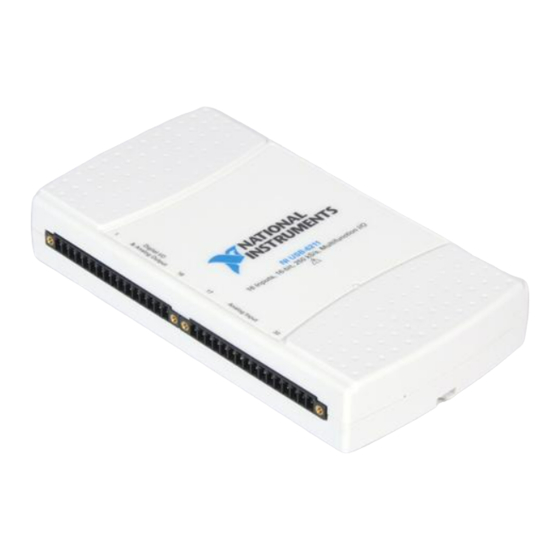
16 AI (16-Bit, 250 kS/s), 2 AO (250 kS/s), 4 DI, 4 DO USB Multifunction I/O Device—The USB‑6211 is a multifunction DAQ device. It offers analog I/O, digital input, digital output, and two 32‑bit counters. The device provides an onboard amplifier designed for fast settling times at high scanning rates. It also features signal streaming technology that gives you DMA-like bidirectional high-speed streaming of data across USB. The device is ideal for test, control, and design applications including portable data logging, field monitoring, embedded OEM, in-vehicle data acquisition, and academic.
The USB‑6211 features a lightweight mechanical enclosure and is bus powered for easy portability. The included NI‑DAQmx driver and configuration utility simplify configuration and measurements.
Ресурсы технической поддержки
![]()
Руководства
Найти документацию для продукта, необходимую для начала работы.
![]()
Библиотека материалов технической поддержки
Исследуйте разнообразные материалы технической поддержки, например информацию о поиске и устранении неполадок и примеры проектов.
![]()
Сообщество
Общайтесь, делитесь решениями и задавайте вопросы другим участникам сообщества NI.
-
Bookmarks
Quick Links
USER GUIDE
NI USB-6211/6218 OEM
There are no product safety, electromagnetic compatibility (EMC), or
Caution
CE marking compliance claims made for the USB-6211/6218 OEM devices.
Conformity to any and all compliance requirements rests with the end product
supplier.
USB-6211
This document provides information about the dimensions, mounting
options, connectors, and other components of the NI USB-6211/6218
OEM devices.
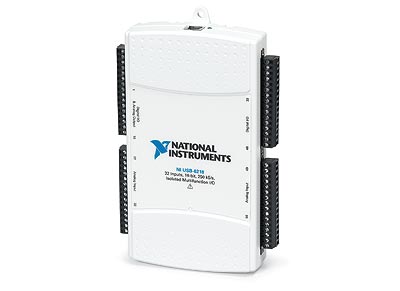
Figure 1 shows the USB-6211 OEM and USB-6218 OEM devices.
Figure 1. USB-621x OEM Devices
Refer to the NI USB-621x Specifications document for USB-6211/6218
specifications and the NI USB-621x User Manual for more information
about USB-6211/6218 devices. You can find all documentation at
.
ni.com/manuals
USB-6218
Summary of Contents for National Instruments USB-6211
Устройства сбора данных с USB-питанием . Устройства сбора данных . Оборудование для системы сбора данных . Оборудование National Instruments . Промышленные компьютеры, контроллеры
Устройства сбора данных серии USB-621x компании National Instruments используют питание от шины USB, при этом они обеспечивают превосходную точность измерений при высоких скоростях работы. Они имеют до 32 каналов аналогового ввода, опрашиваемых с частотой до 250 кГц в одноканальном режиме, 2 аналоговых выхода, до 8 цифровых входов/выходов, возможность индивидуального конфигурирования входных диапазонов для каждого из каналов (4 режима от ±0.2 до ±10 В), линии цифровой синхронизации и два счетчика. Платы NI USB-6215 и USB-6218 имеют встроенную систему изоляции для увеличения точности измерений, повышения безопасности и надежности . Эти USB-модули разработаны специально для мобильных и компактных приложений. Технология Plug-and-play уменьшает время установки и конфигурирования устройства, в то время как наличие винтовых терминалов снижает его стоимость и упрощает подключение сигнальных проводов. Наличие же USB-питания позволяет вам избавиться от ненужных внешних источников.
| Особенности | NI 6210 | NI 6211 | NI 6215 | NI 6218 |
|---|---|---|---|---|
| Шина | USB | USB | USB | USB |
| Аналоговые входы | 16 SE/ 8 DI | 16 SE/ 8 DI | 16 SE/ 8 DI | 32 SE/ 16 DI |
| Частота оцифровки сигналов | 250 кГц | 250 кГц | 250 кГц | 250 кГц |
| Разрешение АЦП (бит) | 16 | 16 | 16 | 16 |
| Встроенное согласование сигналов | — | — | — | — |
| Максимальное входной диапазон | ±10 В | ±10 В | ±10 В | ±10 В |
| Число входных диапазонов | 4 | 4 | 4 | 4 |
| Аналоговый запуск | — | — | — | — |
| Аналоговые выходы | 0 | 2 | 2 | 2 |
| Разрешение ЦАП (бит) | — | 16 | 16 | 16 |
| Максимальная частота работы ЦАП | — | 250 кГц | 250 кГц | 250 кГц |
| Количество цифровых входов | 4 | 4 | 4 | 8 |
| Количество цифровых выходов | 4 | 4 | 4 | 8 |
| Рабочее выходное цифровое напряжение | 5 В (TTL/CMOS) | 5 В (TTL/CMOS) | 5 В (TTL/CMOS) | 5 В (TTL/CMOS) |
| Количество счетчиков, разрешение (бит), частота (МГц) | 2, 32, 80 | 2, 32, 80 | 2, 32, 80 | 2, 32, 80 |
| Изоляция | — | — | да | да |
SE — в режиме с одним заземленным контактом
DI — в дифференциальном режиме
Многофункциональная карта сбора данных NI USB-6211 DAQ серии M 779676-01 |
NI USB-6211 16 бит, 250 kS/s M серии Многофункциональный DAQ, с питанием от шины 16 аналоговых входов (16 бит, 250 Кс/с) 2 аналоговых выхода (16 бит, 250 kS/s); 4 цифровых входного сигнала; 4 цифровых данных; 32-битные счетчики для гибкий передвигаться на автобус с питанием от USB; Встроенные сигнальные соединения для чтения и записи сигнала NI для непрерывной высокоскоростной передачи данных по USB; OEM версии доступны с LabVIEW, LabWindows™/CVI и viial Studio.NET Measurement Studio совместимы с программным обеспечением драйвера NI-DAQmx и программным обеспечением для интерактивной регистрации данных NI LabVIEW SignalExpress LE. NI USB-6211-это многофункциональный DAQ модуль с питанием от шины USB серии M, который поддерживает высокую точность при высоких частотах образцов. Модуль обеспечивает 16 аналоговых входов; 250 kS/s одноканальная частота образца; 2 аналоговых выхода; 4 цифровых входных линии; 4 цифровых выходных линии; каждый канал обладает 4 программируемых входных диапазонов (± 0,2 V постоянного тока до ± 10 V); Цифровой триггер; 2 Счетчики/таймеры. USB-6211 NI предназначен для мобильных или ограниченных по площади приложений. Его установка plug-and-play минимизирует конфигурацию и время установки, в то время как его прямое соединение с винтовыми клеммами сокращает затраты и упрощает сигнальные соединения. Этот продукт не требует внешнего источника питания. Модуль также имеет новую технологию чтения и записи сигнала NI, которая реализует двунаправленный высокоскоростной поток данных DMA на usb-шине. Для получения дополнительной информации о прочтении и написании сигналов NI см. Раздел технических ресурсов. Каждый модуль доступен в OEM версии. Пожалуйста, нажмите на колонку «технические ресурсы» или используйте левую навигацию для ценообразования и технической информации.

Напоминание о кэшбэке: Что бы получить кешбек при покупке этого или другого товара на Aliexpress. Перейдите по ссылке ниже, затем на открывшейся странице авторизуйтесь/зарегистрируйетсь, далее появиться подробная инструкция как получать кэшбэк при покупках на Алиэкспресс.
Кэшбэк в интернет магазинах
Отзывы покупателей
*о других товарах
Отзывы
Здесь вы можете оставить свой отзыв о данном товаре.
Appendix A Device-Specific Information
Table A-2. PWR/ACT LED Status (Continued)
LED State
Single-blink
Double-blink
Device Status
Operating normally. Connected to
USB Hi-Speed port. Refer to the
NI 621x Specifications for more information.
Connected to USB full speed port.
Device performance might be affected. Refer to the NI 621x
Specifications for more information.
USB-6211/6215
USB-6211/6215 Pinout
Figure A-2 shows the pinout of the NI 6211/6215.
For a detailed description of each signal, refer to the
I/O Connector Signal
Descriptions
section of Chapter 3,
Connector Information
.
NI USB-621x User Manual
A-4 ni.com
Appendix A Device-Specific Information
AI 1
AI 9
AI 2
AI 10
AI 3
AI 11
AI SENSE
AI 4
AI 12
AI 5
AI 13
AI GND
AI 6
AI 14
AI 7
AI 15
PFI 0/P0.0 (In)
PFI 1/P0.1 (In)
PFI 2/P0.2 (In)
PFI 3/P0.3 (In)
D GND
PFI 4/P1.0 (Out)
PFI 5/P1.1 (Out)
PFI 6/P1.2 (Out)
PFI 7/P1.3 (Out)
+5 V
D GND
AO 0
AO 1
AO GND
AI 0
AI 8
© National Instruments Corporation
Figure A-2. USB-6211/6215 Pinout
Table A-3. Default NI-DAQmx Counter/Timer Pins
Counter/Timer Signal
CTR 0 SRC
CTR 0 GATE
CTR 0 AUX
CTR 0 OUT
CTR 0 A
CTR 0 Z
Default Terminal Number (Name)
1 (PFI 0)
2 (PFI 1)
1 (PFI 0)
6 (PFI 4)
1 (PFI 0)
2 (PFI 1)
A-5
NI USB-621x User Manual
Appendix A Device-Specific Information
Table A-3. Default NI-DAQmx Counter/Timer Pins
Counter/Timer Signal
CTR 0 B
CTR 1 SRC
CTR 1 GATE
CTR 1 AUX
CTR 1 OUT
CTR 1 A
CTR 1 Z
CTR 1 B
FREQ OUT
Default Terminal Number (Name)
1 (PFI 0)
4 (PFI 3)
3 (PFI 2)
4 (PFI 3)
7 (PFI 5)
4 (PFI 3)
3 (PFI 2)
4 (PFI 3)
8 (PFI 6)
Note For more information about default NI-DAQmx counter inputs, refer to Connecting
Counter Signals in the NI-DAQmx Help or the LabVIEW 8.x Help.
USB-6211/6215 Specifications
Refer to the NI 621x Specifications for more detailed information about the
USB-6211/6215 device.
USB-6211/6215 PWR/ACT LED Indicator
The PWR/ACT LED indicator indicates device status.
Table A-4. PWR/ACT LED Status
LED State
Not lit
On, not blinking
Device Status
Device not powered or device error. Refer to ni.com/support if device is powered.
Device error. Refer to ni.com/support
.
NI USB-621x User Manual
A-6 ni.com
USER GUIDE
NI USB-6211/6218 OEM
This document provides information about the dimensions, mounting
options, connectors, and other components of the NI USB-6211/6218
OEM devices.
Caution
There are no product safety, electromagnetic compatibility (EMC), or
CE marking compliance claims made for the USB-6211/6218 OEM devices.
Conformity to any and all compliance requirements rests with the end product
supplier.
Figure 1 shows the USB-6211 OEM and USB-6218 OEM devices.
Figure 1. USB-621x OEM Devices
Refer to the NI USB-621x Specifications document for USB-6211/6218
specifications and the NI USB-621x User Manual for more information
about USB-6211/6218 devices. You can find all documentation at
ni.com/manuals
.
USB-6211
USB-6218
NATIONAL INSTRUMENTS Решение для тестирования Ethernet в формате PXIe-7902

КОМПЛЕКСНЫЕ УСЛУГИ
Мы предлагаем конкурентоспособные услуги по ремонту и калибровке, а также легкодоступную документацию и ресурсы для бесплатной загрузки.
ПРОДАТЬ ИЗБЫТОК
Мы покупаем новые, бывшие в употреблении списанные и излишки деталей каждой серии Ni.
Мы разрабатываем наилучшее решение в соответствии с вашими индивидуальными потребностями.
- Продать за наличные
- Получить кредит
- Получите сделку по обмену
Преодоление разрыва между производителем и вашей устаревшей тестовой системой.
УСТАРЕВШЕЕ ОБОРУДОВАНИЕ NI В НАЛИЧИИ $ ГОТОВО К ОТПРАВКЕ
У нас есть новые, Новые излишки, отремонтированные, и Восстановленный Аппаратное обеспечение НИ.
ПРОИЗВОДИТЕЛЬ
National Instruments
Номера деталей платы в сборе
(См. Процедуру 1 для процедуры идентификации):
| Номер детали и версия | Описание |
| 194710A-04 или новее | USB-6210 |
| 194710A-03 или новее | USB-6211 |
| 196203A-03L или новее | USB-6211 ОЕМ |
| 197493A-03L или новее | USB-6212 |
| 198402A-03L или новее | USB-6212 МАССОВОЕ СОЕДИНЕНИЕ |
| 190630A-01L или новее | USB-6212 BNC |
| 197504A-03L или новее | USB-6212 ОЕМ |
| 194710A-02 или новее | USB-6215 |
| 197493A-01L или новее | USB-6216 |
| 198402A-01L или новее | USB-6216 МАССОВОЕ СОЕДИНЕНИЕ |
| 190631A-01L или новее | USB-6216 BNC |
| 197504A-01L или новее | USB-6216 ОЕМ |
| 194710A-01 или новее | USB-6218 |
| 190632A-01L или новее | USB-6218 BNC |
| 196203A-01L или новее | USB-6218 ОЕМ |
Энергозависимая память
| Целевые данные | Тип | Размер | Батарея Восстановление | Информация о пользователе1 Доступный | Система Доступный | Процедура санитарной обработки |
| Клеевая логика | ПЛИС 1 | Альтера ЭП1С3 |
Нет | Нет | Да | Цикл Мощность |
| Клеевая логика | ПЛИС 2 | Xilinx XC3S500E |
Нет | Нет | Да | Цикл Мощность |
| Код программы | SRAM | 128 KB | Нет | Нет | Да | Цикл Мощность |
Энергонезависимая память (включая хранилище мультимедиа)
| Целевые данные | Тип | Размер | Батарея Восстановление | Информация о пользователе Доступный | Система Доступный | Санитарная Процедура |
Конфигурация устройства
|
EEPROM | 2 KB | Нет | Нет Да Нет |
Да Да Да |
Ничто Процедура 2 Ничто |
1 Обратитесь к разделу «Термины и определения» для уточнения терминов «Доступно для пользователя и системы».
2 Константы калибровки, хранящиеся на устройстве, содержат информацию для всего рабочего диапазона устройства. Любые последствия частичной самокалибровки можно устранить, выполнив процедуру полной самокалибровки.
Процедуры
Процедура 1 – Идентификация номера детали платы в сборе:
Чтобы определить номер детали и версию сборки платы, обратитесь к этикетке «P/N», нанесенной на поверхность вашего продукта, как показано ниже. Номер детали сборки должен быть отформатирован как «P/N: ######a-vvL», где «a» — буквенная версия сборки платы (например, A, B, C…), а «vv» является идентификатором типа. Если продукт соответствует требованиям RoHS, в конце номера детали можно найти букву «L».
USB-6210/6211/6212/6215/6216/6218/6212 МАССОВОЕ СОЕДИНЕНИЕ/6216 МАССОВОЕ СОЕДИНЕНИЕ — этикетка находится на нижней части корпуса.
USB-6211 OEM/6218 OEM — основная сторона
USB-6212 OEM/6216 OEM — вторичная сторона
USB-6212 BNC/6216 BNC/6218 BNC — этикетка находится на нижней части корпуса.
Процедура 2 – Конфигурация устройства EEPROM (метаданные калибровки):
Доступные пользователю области EEPROM конфигурации устройства доступны через калибровочный интерфейс прикладного программирования (API) в лаборатории.VIEW. Чтобы очистить область метаданных калибровки, выполните следующие действия:
- Чтобы сбросить пароль калибровки, используйте DAQmx Change External Calibration Password.vi, чтобы перезаписать текущий пароль устройства, которое вы хотите сбросить.
- Доступную пользователю область EEPROM конфигурации устройства можно очистить с помощью NI DAQmx API.
Инструкции по очистке этих областей см. www.ni.com/info и введите инфокод DAQmxLOV.
Термины и определения
Мощность цикла:
Процесс полного отключения питания устройства и его компонентов и обеспечения адекватной разрядки. Этот процесс включает в себя полное отключение ПК и/или корпуса, содержащего устройство; перезагрузки недостаточно для завершения этого процесса.
Энергонезависимая память:
Требуется питание для хранения сохраненной информации. При отключении питания от этой памяти ее содержимое теряется.
Память этого типа обычно содержит специфические для приложения данные, такие как захваченные осциллограммы.
Энергонезависимая память:
Питание не требуется для поддержания сохраненной информации. Устройство сохраняет свое содержимое при отключении питания.
Этот тип памяти обычно содержит информацию, необходимую для загрузки, настройки или калибровки продукта, или может включать состояния включения устройства.
Доступно пользователю:
Компонент доступен для чтения и/или записи, так что пользователь может хранить произвольную информацию в компоненте с хоста, используя общедоступный инструмент NI, такой как Driver API, System Configuration API или MAX.
Система доступна:
Компонент доступен для чтения и/или записи с хоста без необходимости физического изменения продукта.
Очистка:
В соответствии со специальной публикацией NIST 800-88, редакция 1, «очистка» — это логический метод очистки данных во всех доступных для пользователя местах хранения для защиты от простых неинвазивных методов восстановления данных с использованием того же интерфейса, доступного пользователю; обычно применяются через стандартные команды чтения и записи на запоминающее устройство.
Санитарная обработка:
Согласно специальной публикации NIST 800-88, редакция 1, «дезинфекция» — это процесс, делающий доступ к «целевым данным» на носителе невозможным для данного уровня усилий. В этом документе очистка — это описанная степень санитарной обработки.
ОБСЛУЖИВАНИЕ
Примечание. Этот документ может быть изменен без предварительного уведомления.
Для самой последней версии.
![]() 1-00-915-6216
1-00-915-6216![]() www.apexwaves.com
www.apexwaves.com![]() sales@apexwaves.com
sales@apexwaves.com
Все товарные знаки, бренды и торговые марки являются собственностью их соответствующих владельцев.
Request a Quote ![]() PXIe-7902
PXIe-7902
Контакт: 866-275-6964
посещение ni.com/руководства | support@ni.com


Документы / Ресурсы
Рекомендации
Устройства сбора данных с USB-питанием . Устройства сбора данных . Оборудование для системы сбора данных . Оборудование National Instruments . Промышленные компьютеры, контроллеры
Устройства сбора данных серии USB-621x компании National Instruments используют питание от шины USB, при этом они обеспечивают превосходную точность измерений при высоких скоростях работы. Они имеют до 32 каналов аналогового ввода, опрашиваемых с частотой до 250 кГц в одноканальном режиме, 2 аналоговых выхода, до 8 цифровых входов/выходов, возможность индивидуального конфигурирования входных диапазонов для каждого из каналов (4 режима от ±0.2 до ±10 В), линии цифровой синхронизации и два счетчика. Платы NI USB-6215 и USB-6218 имеют встроенную систему изоляции для увеличения точности измерений, повышения безопасности и надежности . Эти USB-модули разработаны специально для мобильных и компактных приложений. Технология Plug-and-play уменьшает время установки и конфигурирования устройства, в то время как наличие винтовых терминалов снижает его стоимость и упрощает подключение сигнальных проводов. Наличие же USB-питания позволяет вам избавиться от ненужных внешних источников.
| Особенности | NI 6210 | NI 6211 | NI 6215 | NI 6218 |
|---|---|---|---|---|
| Шина | USB | USB | USB | USB |
| Аналоговые входы | 16 SE/ 8 DI | 16 SE/ 8 DI | 16 SE/ 8 DI | 32 SE/ 16 DI |
| Частота оцифровки сигналов | 250 кГц | 250 кГц | 250 кГц | 250 кГц |
| Разрешение АЦП (бит) | 16 | 16 | 16 | 16 |
| Встроенное согласование сигналов | — | — | — | — |
| Максимальное входной диапазон | ±10 В | ±10 В | ±10 В | ±10 В |
| Число входных диапазонов | 4 | 4 | 4 | 4 |
| Аналоговый запуск | — | — | — | — |
| Аналоговые выходы | 0 | 2 | 2 | 2 |
| Разрешение ЦАП (бит) | — | 16 | 16 | 16 |
| Максимальная частота работы ЦАП | — | 250 кГц | 250 кГц | 250 кГц |
| Количество цифровых входов | 4 | 4 | 4 | 8 |
| Количество цифровых выходов | 4 | 4 | 4 | 8 |
| Рабочее выходное цифровое напряжение | 5 В (TTL/CMOS) | 5 В (TTL/CMOS) | 5 В (TTL/CMOS) | 5 В (TTL/CMOS) |
| Количество счетчиков, разрешение (бит), частота (МГц) | 2, 32, 80 | 2, 32, 80 | 2, 32, 80 | 2, 32, 80 |
| Изоляция | — | — | да | да |
SE — в режиме с одним заземленным контактом
DI — в дифференциальном режиме