- Manuals
- Brands
- Yamaha Manuals
- Motorcycle
- Road Star XV1600A 2000
- Owner’s manual
-
Contents
-
Table of Contents
-
Troubleshooting
-
Bookmarks
Related Manuals for Yamaha Road Star XV1600A 2000
Summary of Contents for Yamaha Road Star XV1600A 2000
-
Page 1
XV1600A OWNER’S MANUAL… -
Page 2
INTRODUCTION EAU00000 Congratulations on your purchase of the Yamaha Road Star™. This model is the result of Yamaha’s vast experience in the production of fine sporting, touring, and pacesetting racing machines. It represents the high degree of craftsmanship and reliability that have made Yamaha a leader in these fields. -
Page 3
This manual should be considered a permanent part of this motorcycle and should remain with it even if the motorcycle is subsequently sold. Yamaha continually seeks advancements in product design and quality. Therefore, while this manual contains the most current product information available at the time of printing, there may be minor discrepancies between your motorcycle and this manual. -
Page 4
IMPORTANT MANUAL INFORMATION EW000002 WARNING PLEASE READ THIS MANUAL CAREFULLY AND COMPLETELY BEFORE OPERATING THIS MOTORCYCLE. -
Page 5
IMPORTANT MANUAL INFORMATION EAU03337 XV1600AM OWNER’S MANUAL © 2000 by Yamaha Motor Co., Ltd. 1st Edition, March 2000 All rights reserved. Any reprinting or unauthorized use without the written permission of Yamaha Motor Co., Ltd. is expressly prohibited. Printed in Japan. -
Page 6: Table Of Contents
TABLE OF CONTENTS 1 SAFETY INFORMATION 2 DESCRIPTION 3 INSTRUMENT AND CONTROL FUNCTIONS 4 PRE-OPERATION CHECKS 5 OPERATION AND IMPORTANT RIDING POINTS 6 PERIODIC MAINTENANCE AND MINOR REPAIR 7 MOTORCYCLE CARE AND STORAGE 8 SPECIFICATIONS 9 CONSUMER INFORMATION INDEX…
-
Page 8: Safety Information
SAFETY INFORMATION Safe riding ………………1-1 Protective apparel …………….1-3 Modifications ………………1-3 Loading and accessories …………..1-3 Gasoline and exhaust gas…………..1-5 Location of important labels ………….. 1-7…
-
Page 9: Safe Riding
S AFETY INFORMATION EAU01771 MOTORCYCLES ARE SINGLE TRACK VEHICLES. THEIR SAFE USE AND OPERATION ARE DEPENDENT UPON THE USE OF PROPER RIDING TECHNIQUES AS WELL AS THE EXPERTISE OF THE OPERATOR. EVERY OPERATOR SHOULD KNOW THE FOLLOWING REQUIREMENTS BEFORE RIDING THIS MOTORCYCLE. HE OR SHE SHOULD: 1.
-
Page 10
SAFETY INFORMATION 4. Many accidents involve inexperienced operators. In fact, many operators who have been involved in accidents do not even have a current motorcycle license. a. Make sure that you are qualified and that you only lend your motorcycle to other qualified opera- tors. -
Page 11: Protective Apparel
6. Passengers should also observe the precautions mentioned above. Modifications Modifications made to this motorcycle not approved by Yamaha, or the removal of original equipment, may render the motorcycle unsafe for use and may cause severe personal injury. Modifications may also make your motorcycle illegal to use.
-
Page 12
Genuine Yamaha accessories have been specifically designed for use on this motorcycle. Since Yamaha cannot test all other accessories that may be available, you must personally be responsible for the proper selection, installation and use of non-Yamaha accessories. Use extreme caution when selecting and installing any accessories. -
Page 13: Gasoline And Exhaust Gas
SAFETY INFORMATION a. Accessories fitted to the handlebar or the front fork area can create instability due to improper weight distribution or aerodynamic changes. If accessories are added to the handlebar or front fork area, they must be as lightweight as possible and should be kept to a minimum. b.
-
Page 14
SAFETY INFORMATION a. The engine and exhaust system may be hot, therefore, park the motorcycle in a place where pe- destrians or children are not likely to touch these hot areas. b. Do not park the motorcycle on a slope or soft ground, otherwise it may fall over. c. -
Page 15: Location Of Important Labels
SAFETY INFORMATION EAU02977 Location of important labels Please read the following important labels carefully before operating this motorcycle. WARNING Before you operate this vehicle, read the owner’s manual. English 3HP-21568-00 4AA-22259-40…
-
Page 16: Description
DESCRIPTION Left view ……………….. 2-1 Right view ………………2-2 Controls and instruments …………..2-3…
-
Page 17
D ESCRIPTION EAU00026 Left view 1. Shift pedal (page 3-7) 6. Helmet holder (page 3-12) 2. Starter (choke) knob (page 3-10) 7. Rear turn signal lights (page 6-34) 3. Fuel cock (page 3-9) 8. Tail/brake light (page 6-34) 4. Rider seat (page 3-11) 9. -
Page 18
DESCRIPTION Right view 10. Passenger footrest 16. Throttle stop screw (page 6-16) 11. Passenger seat 17. Brake pedal (page 3-7) 12. Fuel tank (page 3-9) 18. Rider footrest 13. Fuel tank cap (page 3-8) 19. Rear shock absorber spring preload 14. -
Page 19
DESCRIPTION Controls and instruments 1. Clutch lever (page 3-6) 5. Right handlebar switches (page 3-6) 2. Left handlebar switches (page 3-5) 6. Throttle grip (page 6-16) 3. Speedometer unit (page 3-3) 7. Brake lever (page 3-7) 4. Main switch/steering lock (page 3-1) -
Page 20: Instrument And Control Functions
INSTRUMENT AND CONTROL FUNCTIONS Main switch/steering lock …………..3-1 Indicator and warning lights …………. 3-2 Speedometer unit …………….3-3 Fuel gauge ………………3-4 Self-diagnosis device ……………. 3-4 Clock ………………..3-4 Handlebar switches …………….3-5 Clutch lever ………………3-6 Shift pedal ………………3-7 Brake lever ………………
-
Page 21: Main Switch/Steering Lock
I NSTRUMENT AND CONTROL FUNCTIONS EAU00027 1. Push. 2. Turn. EAU00029 EAU00040 Main switch/steering lock LOCK EW000016 The steering is locked, and all electrical WARNING The main switch/steering lock controls systems are off. The key can be re- the ignition and lighting systems, and is Never turn the key to “OFF”…
-
Page 22: Indicator And Warning Lights
Fuel level warning light “ ” the engine is defective. When this oc- This warning light comes on when the curs, have the Yamaha dealer check fuel level drops below approximately the self-diagnosis system. 3.5 L. When this occurs, turn the fuel cock lever to the “RES”…
-
Page 23: Speedometer Unit
INSTRUMENT AND CONTROL FUNCTIONS Pushing the mode button (left) switch- es the display between the odometer mode “ODO” and the tripmeter modes “TRIP A” and “TRIP B” in the following order: CB-27E TRIP A TRIP B 1. Odometer/tripmeter/clock 2. Speedometer To reset a tripmeter, select it by push- 3.
-
Page 24: Fuel Gauge
If this occurs, refuel as come on or the fuel level warning light soon as possible. will flash. If this occurs, have a Yamaha 1. Clock dealer check the motorcycle. NOTE: 2.
-
Page 25: Handlebar Switches
INSTRUMENT AND CONTROL FUNCTIONS 4. Push the right button to change the hours. 5. Push the left button and only the minute display will flash. To set the clock: EAU00118 Handlebar switches 6. Push the right button to change 1. Turn the key to “ON”. the minutes.
-
Page 26: Clutch Lever
INSTRUMENT AND CONTROL FUNCTIONS EAU00127 3. Turn signal switch To signal a right-hand turn, push this switch to “ ”. To signal a left-hand turn, push this switch to “ ”. When released, the switch returns to the cen- ter position. To cancel the turn signal lights, push the switch in after it has re- turned to the center position.
-
Page 27: Shift Pedal
INSTRUMENT AND CONTROL FUNCTIONS 1. Shift pedal 1. Brake lever 1. Brake pedal EAU01215 EAU00158 EAU00162 Shift pedal Brake lever Brake pedal The shift pedal is located on the left The brake lever is located at the right The brake pedal is on the right side of side of the engine and is used in com- handlebar grip.
-
Page 28: Fuel Tank Cap
INSTRUMENT AND CONTROL FUNCTIONS NOTE: The fuel tank cap cannot be installed unless the key is in the lock. In addition, the key cannot be removed if the cap is not properly installed and locked. EW000024 WARNING Make sure that the fuel tank cap is properly installed before riding.
-
Page 29: Fuel
INSTRUMENT AND CONTROL FUNCTIONS EAU00185 OFF: closed position CAUTION: Immediately wipe off spilled fuel with a clean, dry, soft cloth, since fuel may deteriorate painted surfac- es or plastic parts. EAU00192 Recommended fuel: 1. Filler tube Regular gasoline 2. Fuel level EAU03050 For Australia: Fuel cock…
-
Page 30: Starter (Choke) Knob
INSTRUMENT AND CONTROL FUNCTIONS ON: normal position RES: reserve position EAU03032 Starter (choke) knob With the lever in this position, fuel flows This indicates reserve. If you run out of Starting a cold engine requires a richer to the carburetor. Normal riding is done fuel while riding, move the lever to this air-fuel mixture, which is supplied by with the lever in this position.
-
Page 31: Locking The Steering With A Padlock
INSTRUMENT AND CONTROL FUNCTIONS 1. Projection 2. Seat holder EAU03372 EAU01737 Locking the steering with a Rider seat To install the rider seat padlock 1. Insert the projection on the rear of To remove the rider seat the rider seat into the seat holder In addition to the main switch/steering 1.
-
Page 32: Helmet Holder
INSTRUMENT AND CONTROL FUNCTIONS EW000030 WARNING Never ride with a helmet attached to the helmet holder, since the helmet may hit objects, causing loss of control and possibly an accident. To release the helmet from the hel- met holder 1. Helmet holder Remove the rider seat, remove the hel- EAU01819 met from the helmet holder, and then…
-
Page 33: Adjusting The Shock Absorber Assembly
INSTRUMENT AND CONTROL FUNCTIONS 1. Locknut 1. Special wrench A. Distance A 2. Adjusting nut 2. To increase the spring preload Spring preload: EAU00293 and thereby harden the suspen- Adjusting the shock absorber Minimum (soft): sion, turn the adjusting nut in di- assembly Distance A = 42.5 mm rection a.
-
Page 34
Do not deform or damage the gas cylinder in any way, as this will result in poor damping per- formance. Always have a Yamaha dealer service the shock absorber. 3-14… -
Page 35: Sidestand
It cuts the running engine when check this system regularly as de- the sidestand is moved down. scribed below and have a Yamaha Periodically check the operation of the dealer repair it if it does not function ignition circuit cut-off system according properly.
-
Page 36
5. Push the start switch. Does the engine start? The neutral switch may be defective. The motorcycle should not be ridden until checked by a Yamaha dealer. With the engine still running: 6. Move the sidestand up. 7. Keep the clutch lever pulled. -
Page 38: Pre-Operation Checks
PRE-OPERATION CHECKS Pre-operation check list …………..4-1…
-
Page 39
P RE-OPERATION CHECKS EAU01114 The condition of a vehicle is the owner’s responsibility. Vital components can start to deteriorate quickly and unexpectedly, even if the vehicle remains unused (for example, as a result of exposure to the elements). Any damage, fluid leakage or loss of tire air pressure could have serious consequences. -
Page 40
PRE-OPERATION CHECKS ITEM CHECKS PAGE • Check fuel level. Fuel • Add fuel if necessary. Lights, signals and • Check operation. — switches NOTE: Pre-operation checks should be made each time the motorcycle is used. Such an inspection can be accomplished in a very short time;… -
Page 42: Operation And Important Riding Points
OPERATION AND IMPORTANT RIDING POINTS Starting and warming up a cold engine ……….5-1 Starting a warm engine …………..5-3 Shifting ………………..5-3 Tips for reducing fuel consumption ……….. 5-4 Engine break-in …………….. 5-4 Parking ………………..5-5…
-
Page 43: Starting And Warming Up A Cold Engine
Before starting engine, their functions before riding. check the function of the igni- Consult a Yamaha dealer re- tion circuit cut-off system ac- garding any control or function cording procedure that you do not thoroughly un- described on page 3-15.
-
Page 44
When the transmission is in the neutral position, the neutral indicator light NOTE: The engine is warm when it responds should be on, otherwise have a normally to the throttle with the starter Yamaha dealer check the electrical cir- (choke) turned off. cuit. -
Page 45: Starting A Warm Engine
OPERATION AND IMPORTANT RIDING POINTS EAU01258 EC000048 Starting a warm engine CAUTION: Follow the same procedure as for start- Even with the transmission in ing a cold engine with the exception the neutral position, do not that the starter (choke) is not required coast for long periods of time when the engine is warm.
-
Page 46: Tips For Reducing Fuel Consumption
If any engine trouble should occur correct operating clearances. During during the engine break-in period, this period, prolonged full-throttle oper- immediately have a Yamaha dealer ation or any condition that might result check the vehicle. in engine overheating must be avoided.
-
Page 47: Parking
OPERATION AND IMPORTANT RIDING POINTS EAU00457 Parking When parking, stop the engine, re- move the key from the main switch, and then turn the fuel cock lever to “OFF”. EW000058 WARNING Since the engine and exhaust system can become very hot, park in a place where pedestri- ans or children are not likely to touch them.
-
Page 48: Periodic Maintenance And Minor Repair
PERIODIC MAINTENANCE AND MINOR REPAIR Owner’s tool kit …………6-1 Checking the brake fluid level ……6-23 Periodic maintenance and lubrication chart ..6-3 Changing the brake fluid ……..6-24 Removing and installing the panel …….6-6 Drive belt slack ……….6-24 Checking the spark plugs ……..6-7 Checking and lubricating the brake and shift pedals …………
-
Page 49: Owner’s Tool Kit
VALS MAY NEED TO BE SHORT- ENED. EW000060 WARNING If you are not familiar with motor- cycle maintenance work, have a Yamaha dealer do it for you. 1. Owner’s tool kit EAU00464 EAU03394 Safety is an obligation of the owner. Owner’s tool kit Periodic inspection, adjustment and lu- The owner’s tool kit is located under…
-
Page 50
PERIODIC MAINTENANCE AND MINOR REPAIR NOTE: If you do not have the tools or experi- ence required for a particular job, have a Yamaha dealer perform it for you. EW000063 WARNING Modifications approved Yamaha may cause loss of perfor- mance and render the vehicle un- safe for use. -
Page 51: Periodic Maintenance And Lubrication Chart
PERIODIC MAINTENANCE AND MINOR REPAIR EAU00473 Periodic maintenance and lubrication chart CP-01E Every Every Initial Annual ITEM CHECKS AND MAINTENANCE JOBS 1,000 km check 6,000 km 12,000 km • Check fuel hoses for cracks or damage. √ √ Fuel line •…
-
Page 52
PERIODIC MAINTENANCE AND MINOR REPAIR Every Every Initial Annual ITEM CHECKS AND MAINTENANCE JOBS 1,000 km check 6,000 km 12,000 km • Check bearings for looseness or damage. √ Wheel bearings • Replace if necessary. • Check operation and for excessive play. •… -
Page 53
• Correct if necessary. switches • Adjust headlight beam if necessary. * Since these items require special tools, data and technical skills, have a Yamaha dealer perform the service. EAU03206 NOTE: The annual checks must be performed every year except if a 6,000 km or 12,000 km maintenance is performed instead. -
Page 54: Removing And Installing The Panel
PERIODIC MAINTENANCE AND MINOR REPAIR 1. Panel A 1. Bolt EAU01777 EAU00491 Removing and installing the Panel A To remove the panel panel Remove the bolt, and then pull the pan- The panel shown above needs to be el off as shown. removed to perform some of the main- tenance jobs described in this chapter.
-
Page 55: Checking The Spark Plugs
Do not attempt to diagnose such threads. problems yourself. Instead, have a Yamaha dealer check the motorcycle. Tightening torque: If a spark plug shows signs of electrode Spark plug: erosion and excessive carbon or other 18 Nm (1.8 m·kg)
-
Page 56: Engine Oil And Oil Filter Cartridge
PERIODIC MAINTENANCE AND MINOR REPAIR ECA00021 EAU03399* 2. Remove the rider seat. (See page Engine oil and oil filter CAUTION: 3-11 for rider seat removal and in- cartridge Do not use any tools to remove or stallation procedures.) The engine oil level should be checked install the spark plug cap, otherwise 3.
-
Page 57
PERIODIC MAINTENANCE AND MINOR REPAIR 1. Engine oil filler cap 1. Dipstick 1. Engine oil drain bolt (crankcase) 2. Maximum level 4. Wait a few minutes until the oil set- To change the engine oil (with or 3. Minimum level tles, remove the oil filler cap, wipe without oil filter cartridge replace- NOTE:… -
Page 58
20 Nm (2.0 m·kg) NOTE: An oil filter wrench is available at a 8. Pour only 2.5 L of the specified Yamaha dealer. amount of recommended engine 5. Apply a thin coat of engine oil to oil through the filler hole, insert the… -
Page 59: Transfer Case Oil
PERIODIC MAINTENANCE AND MINOR REPAIR 10. Remove the engine oil filler cap, EC000072 EAU03395 Transfer case oil CAUTION: and then gradually fill the oil tank The transfer case oil level should be In order to prevent clutch slip- with the remaining oil quantity checked before each ride.
-
Page 60
PERIODIC MAINTENANCE AND MINOR REPAIR 5. Remove the oil filler cap, add the specified amount of the recom- mended transfer case oil, and then install and tighten the oil filler cap. Recommended transfer case oil: See page 8-2. Oil quantity: 0.4 L 1. -
Page 61: Cleaning The Air Filter Element
PERIODIC MAINTENANCE AND MINOR REPAIR 1. Bolt (× 4) 1. Air filter joint clamp screw 1. Screw (× 2) 2. Air filter case cover 2. Hose (× 2) 2. Loosen the air filter joint clamp 3. Remove the air filter case cover by EAU03396 screw, and then slightly pull the air Cleaning the air filter element…
-
Page 62
PERIODIC MAINTENANCE AND MINOR REPAIR 1. Screw (× 2) 1. Hose (× 2) 2. Hose 6. Lightly tap the air filter element to 8. Install the air filter case cover by 5. Remove the air filter element by remove most of the dust and dirt, installing the screws. -
Page 63: Adjusting The Carburetor
Therefore, most car- checked and, if necessary, adjusted as buretor adjustments should be left to a follows at the intervals specified in the Yamaha dealer, who has the neces- periodic maintenance and lubrication sary professional knowledge and expe- chart.
-
Page 64: Adjusting The Throttle Cable Free Play
If the specified idling speed cannot be from occurring, the valve clearance obtained as described above, have a must be adjusted by a Yamaha dealer Yamaha dealer make the adjustment. at the intervals specified in the periodic maintenance and lubrication chart.
-
Page 65: Tires
PERIODIC MAINTENANCE AND MINOR REPAIR EWA00011 EWA00012 WARNING WARNING Tire inflation pressure should be Because loading has an enormous impact on the handling, braking, per- checked and adjusted when the formance and safety characteristics temperature of the tire equals the of your motorcycle, you should keep ambient air temperature.
-
Page 66
Yamaha dealer immediately and quality product. have the tire replaced. 6-18… -
Page 67: Spoke Wheels
1. Adjusting nut age before each ride. If any dam- 2. Adjusting nut 2. Locknut age is found, have a Yamaha c. Clutch lever free play 3. If the specified clutch lever free dealer replace the wheel. Do not EAU00694…
-
Page 68: Adjusting The Brake Lever Free Play
1. Locknut system. If there is air in the hy- 2. Adjusting bolt draulic system, have a Yamaha c. Brake lever free play dealer bleed the system before EAU00696 Adjusting the brake lever free operating the motorcycle.
-
Page 69: Adjusting The Brake Pedal Position
If there is air in the hydraulic system, have a Yamaha dealer bleed the system be- fore operating the motorcycle. Air in the hydraulic system will diminish a. Distance between brake pedal and footrest 1.
-
Page 70: Checking The Front And Rear Brake Pads
Yamaha dealer replace the appeared, have a Yamaha dealer re- brake pads as a set. place the brake pads as a set.
-
Page 71: Checking The Brake Fluid Level
As the brake pads wear, it is nor- mal for the brake fluid level to gradually go down. However, if the brake fluid level goes down sud- denly, have a Yamaha dealer 1. Minimum level mark 1. Minimum level mark check the cause.
-
Page 72: Changing The Brake Fluid
PERIODIC MAINTENANCE AND MINOR REPAIR EAU03238 Changing the brake fluid Have a Yamaha dealer change the brake fluid at the intervals specified in the periodic maintenance and lubrica- tion chart. In addition, have the oil seals of the brake master cylinder and caliper…
-
Page 73
PERIODIC MAINTENANCE AND MINOR REPAIR 1. Wheel axle nut 1. Caliper bracket bolt 1. Adjusting bolt (× 2) 2. Locknut (× 2) EAU01748 To adjust the drive belt slack 2. Loosen the drive belt puller lock- 1. Loosen the rear wheel axle nut nut on each side of the swingarm. -
Page 74: Checking And Lubricating The Brake And Shift Pedals
PERIODIC MAINTENANCE AND MINOR REPAIR ECA00025 CAUTION: Improper drive belt slack will over- load the engine. Keep the drive belt slack within the specified range. 5. Tighten the axle nut and the brake caliper bracket bolt to the specified torques. Tightening torques: EAU03199 Axle nut:…
-
Page 75: Checking And Lubricating The Brake And Clutch Levers
Recommended lubricant: EW000113 WARNING Lithium-soap-based grease If the sidestand does not move up (all-purpose grease) and down smoothly, have a Yamaha dealer check or repair it. Recommended lubricant: Lithium-soap-based grease (all-purpose grease) 6-27…
-
Page 76: Checking The Front Fork
EC000098 CAUTION: If any damage is found or the front fork does not operate smoothly, have a Yamaha dealer check or re- pair it. 6-28…
-
Page 77: Checking The Wheel Bearings
This motorcycle is equipped with a ward and backward. If any free sealed-type (MF) battery, which does play can be felt, have a Yamaha not require any maintenance. There is dealer check or repair the steer- no need to check the electrolyte or to ing.
-
Page 78
Batteries produce explosive hy- To charge the battery WARNING drogen gas. Therefore, keep Have a Yamaha dealer charge the bat- Electrolyte is poisonous and sparks, flames, cigarettes, etc., tery as soon as possible if it seems to dangerous since it contains sul- away from the battery and pro- have discharged. -
Page 79: Replacing The Fuses
Specified fuses: 5. Odometer fuse cess to a sealed-type (MF) bat- Main fuse: 30 A 6. Spare fuse (× 3) tery charger, have a Yamaha Ignition fuse: 15 A EAU01749 dealer charge your battery. Replacing the fuses Signaling system fuse:…
-
Page 80: Replacing The Headlight Bulb
EAU03188 4. If the fuse immediately blows Replacing the headlight bulb 2. Disconnect the headlight coupler, again, have a Yamaha dealer This motorcycle is equipped with a and then remove the headlight unit check the electrical system. quartz bulb headlight. If the headlight and bulb cover.
-
Page 81
5. Install the bulb cover, and then connect the coupler. 6. Install the headlight unit by install- ing the screws. 7. Have a Yamaha dealer adjust the headlight beam if necessary. 1. Headlight bulb holder 1. Do not touch this area. -
Page 82: Replacing A Turn Signal Light Bulb Or The Tail/Brake Light Bulb
However, should your motorcycle 1. Remove the lens by removing the require any repair, take it to a Yamaha screws. dealer, whose skilled technicians have 2. Remove the defective bulb by…
-
Page 83: Troubleshooting Chart
Remove the spark plugs and check the electrodes. The engine does not start. Have a Yamaha dealer check the vehicle. Check the battery. 4. Battery The engine turns over The battery is good.
-
Page 84: Motorcycle Care And Storage
MOTORCYCLE CARE AND STORAGE Care ………………..7-1 Storage ………………..7-4…
-
Page 85
M OTORCYCLE CARE AND STORAGE EAU03398 Before cleaning Cleaning 1. Cover the muffler outlets with plas- ECA00010 CAUTION: tic bags after the engine has Avoid using strong acidic wheel cooled down. cleaners, especially on spoked 2. Make sure that all caps and covers wheels. -
Page 86
MOTORCYCLE CARE AND STORAGE Do not use any harsh chemical For motorcycles equipped with After riding in the rain, near the sea or products on plastic parts. Be a windshield: Do not use strong on salt-sprayed roads sure to avoid using cloths or cleaners or hard sponges as Since sea salt or salt sprayed on roads sponges which have been in… -
Page 87
MOTORCYCLE CARE AND STORAGE After cleaning EWA00001 NOTE: WARNING Salt sprayed on roads in the winter may 1. Dry the motorcycle with a chamois remain well into spring. Make sure that there is no oil or or an absorbing cloth. wax on the brakes or tires. -
Page 88
4. Fill up the fuel tank and add fuel against dust with a porous cover. NOTE: stabilizer (if available) to prevent ECA00014 Consult a Yamaha dealer for advice on the fuel tank from rusting and the CAUTION: what products to use. fuel from deteriorating. -
Page 89
MOTORCYCLE CARE AND STORAGE a. Remove the spark plug caps and 6. Lubricate all control cables and 9. Remove the battery and fully spark plugs. the pivoting points of all levers and charge it. Store it in a cool, dry b. -
Page 90: Specifications
SPECIFICATIONS Specifications ………………8-1 Conversion table …………….8-5…
-
Page 91
S PECIFICATIONS EAU01038 Specifications CS-01E Model XV1600A Engine oil Dimensions Type -20 -10 10 20 30 40 50 ˚C Overall length 2,500 mm SAE 10W-30 Overall width 980 mm Overall height 1,140 mm SAE 10W-40 Seat height 710 mm SAE 15W-40 Wheelbase 1,685 mm SAE 20W-40… -
Page 92
SPECIFICATIONS Transfer case oil Secondary reduction ratio 2.320 Type SAE80API “GL-4” Hypoid Gear Transmission type Constant-mesh, 5-speed Operation Left foot Quantity 0.4 L Gear ratio Air filter Dry type element 2.438 Fuel 1.579 Type Regular gasoline 1.160 Unleaded fuel only 0.906 (for Australia) 0.750… -
Page 93
SPECIFICATIONS Maximum load* 196 kg Rear Tire air pressure Type Single disc brake (measured on cold tires) Operation Right foot Up to 90 kg* Fluid DOT 4 Front 250 kPa (2.50 kgf/cm , 2.50 bar) Suspension Rear 250 kPa (2.50 kgf/cm , 2.50 bar) Front 90 kg–maximum*… -
Page 94
SPECIFICATIONS Headlight type Quartz bulb (halogen) Bulb voltage, wattage × quantity 12 V, 60/55 W × 1 Headlight 12 V, 5/21 W × 1 Tail/brake light 12 V, 21 W × 2 Front turn signal light 12 V, 21 W × 2 Rear turn signal light 14 V, 0.6 W ×… -
Page 95
SPECIFICATIONS EAU01064 Conversion table CS-02E Conversion table All specification data in this manual are listed in SI and METRIC TO IMPERIAL METRIC UNITS. Metric unit Multiplier Imperial unit Use this table to convert METRIC unit data to IMPERIAL m·kg 7.233 ft·lb m·kg 86.794… -
Page 96: Consumer Information
CONSUMER INFORMATION Identification numbers …………… 9-1 Key identification number …………..9-1 Vehicle identification number …………. 9-1 Model label ………………9-2 Motorcycle noise regulation (for Australia) ……..9-2…
-
Page 97
Record the key identification number, vehicle identification number and mod- el label information in the spaces pro- vided below for assistance when ordering spare parts from a Yamaha dealer or for reference in case the vehi- cle is stolen. 1. Key identification number 1. -
Page 98
This in- (b) The use of the vehicle after such formation will be needed when ordering device or element of design has spare parts from a Yamaha dealer. been removed or rendered inoper- ative by any person. -
Page 99
I NDEX 1 0 — High beam indicator light ….3-2 Neutral indicator light ……3-2 Air filter element, cleaning ……6-13 Engine break-in ……..5-4 Turn signal indicator light ….3-2 Engine idling speed ……. 6-15 Instrument and control functions ….3-1 Engine oil and oil filter cartridge ….6-8 Battery ………..6-29 Brake and clutch levers, checking and Key identification number ……9-1… -
Page 100
INDEX Safety information……..1-1 Valve clearance, adjusting ….6-16 Self-diagnosis device……. 3-4 Vehicle identification number….9-1 Shifting ………… 5-3 Shift pedal ……….3-7 Wheel bearings, checking ….. 6-29 Shock absorber assembly, adjusting ..3-13 Wheels……….6-19 Sidestand ……….3-15 Sidestand, checking and lubricating..6-27 Spark plugs, checking …… -
Page 103
PRINTED ON RECYCLED PAPER YAMAHA MOTOR CO., LTD. 5JA-28199-21 PRINTED IN JAPAN 2000 · 3 — 0.3 × 1 CR…


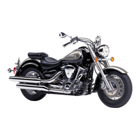
Congratulations on your purchase of the Yamaha Road Star™/Road Star™ Silverado™. This model is the result of Yamaha’s vast experience in the production of fine sporting, touring, and pacesetting racing machines. It represents the high degree of craftsmanship and reliability that have made Yamaha a leader in these fields.
This manual will give you an understanding of the operation, inspection, and basic maintenance of this motorcycle. If you have any questions concerning the operation or maintenance of your motorcycle, please consult a Yamaha dealer.
The design and manufacture of this Yamaha motorcycle fully comply with the emissions standards for clean air applicable at the date of manufacture. Yamaha has met these standards without reducing the performance or economy of operation of the motorcycle. To maintain these high standards, it is important that you and your Yamaha dealer pay close attention to the recommended maintenance schedules and operating instructions contained within this manual.
IMPORTANT MANUAL INFORMATION |
EAU00003 |
Particularly important information is distinguished in this manual by the following notations:
The Safety Alert Symbol means ATTENTION! BECOME ALERT! YOUR SAFETY IS
INVOLVED!
|
WARNING |
Failure to follow WARNING instructions could result in severe injury or death to the |
|
|
motorcycle operator, a bystander or a person inspecting or repairing the motorcycle. |
||
|
CAUTION: |
A CAUTION indicates special precautions that must be taken to avoid damage to the |
|
|
motorcycle. |
||
NOTE: A NOTE provides key information to make procedures easier or clearer.
NOTE:
●This manual should be considered a permanent part of this motorcycle and should remain with it even if the motorcycle is subsequently sold.
●Yamaha continually seeks advancements in product design and quality. Therefore, while this manual contains the most current product information available at the time of printing, there may be minor discrepancies between your motorcycle and this manual. If you have any questions concerning this manual, please consult your Yamaha dealer.

IMPORTANT MANUAL INFORMATION
 WARNING
PLEASE READ THIS MANUAL AND THE “YOU AND YOUR MOTORCYCLE: RIDING TIPS” BOOKLET CAREFULLY AND COMPLETELY BEFORE OPERATING THIS MOTORCYCLE. DO NOT ATTEMPT TO OPERATE THIS MOTORCYCLE UNTIL YOU HAVE ATTAINED ADEQUATE KNOWLEDGE OF ITS CONTROLS AND OPERATING FEATURES AND UNTIL YOU HAVE BEEN TRAINED IN SAFE AND PROPER RIDING TECHNIQUES. REGULAR INSPECTIONS AND CAREFUL MAINTENANCE, ALONG WITH GOOD RIDING SKILLS, WILL ENSURE THAT YOU SAFELY ENJOY THE CAPABILITIES AND THE RELIABILITY OF THIS MOTORCYCLE.
IMPORTANT MANUAL INFORMATION
AFFIX DEALER
LABEL HERE
XV16AP(C)/XV1600AS(C)/XV16ATP(C)
OWNER’S MANUAL
© 2001 by Yamaha Motor Corporation, U.S.A. 1st Edition, May 2001
All rights reserved.
Any reprinting or unauthorized use without the written permission of Yamaha Motor Corporation, U.S.A. is expressly prohibited.
Printed in Japan.
P/N LIT-11626-15-18

TABLE OF CONTENTS
|
1 |
SAFETY INFORMATION |
1 |
|
|
2 |
DESCRIPTION |
2 |
|
|
3 |
INSTRUMENT AND CONTROL FUNCTIONS |
3 |
|
|
4 |
PRE-OPERATION CHECKS |
4 |
|
|
5 |
OPERATION AND IMPORTANT RIDING POINTS |
5 |
|
|
6 |
PERIODIC MAINTENANCE AND MINOR REPAIR |
6 |
|
|
7 |
MOTORCYCLE CARE AND STORAGE |
7 |
|
|
8 |
SPECIFICATIONS |
8 |
|
|
9 |
CONSUMER INFORMATION |
9 |
|
INDEX

SAFETY INFORMATION |
|||||
|
Safe riding ……………………………………………………………………………… |
1-1 |
||||
|
Protective apparel |
1-3 |
||||
|
1 |
|||||
|
Modifications |
1-3 |
||||
|
………………………………………………………….Loading and accessories |
1-3 |
||||
|
Gasoline and exhaust gas………………………………………………………… |
1-5 |
||||
|
Location of important labels …………………………………………………….. |
1-7 |
||||

|
1-SAFETY INFORMATION |
EAU03633 |
MOTORCYCLES ARE SINGLE TRACK VEHICLES. THEIR SAFE USE AND OPERATION ARE DEPENDENT UPON THE USE OF PROPER RIDING TECHNIQUES AS WELL AS THE EXPERTISE OF THE OPERATOR. EVERY OPERATOR SHOULD KNOW THE FOLLOWING REQUIREMENTS
1 BEFORE RIDING THIS MOTORCYCLE. HE OR SHE SHOULD:
1.OBTAIN THOROUGH INSTRUCTIONS FROM A COMPETENT SOURCE ON ALL ASPECTS OF MOTORCYCLE OPERATION.
2.OBSERVE THE WARNINGS AND MAINTENANCE REQUIREMENTS IN THE OWNER’S MANUAL.
3.OBTAIN QUALIFIED TRAINING IN SAFE AND PROPER RIDING TECHNIQUES.
4.OBTAIN PROFESSIONAL TECHNICAL SERVICE AS INDICATED BY THE OWNER’S MANUAL AND/OR WHEN MADE NECESSARY BY MECHANICAL CONDITIONS.
Safe riding
1.Always make pre-operation checks. Careful checks may help prevent an accident.
2.This motorcycle is designed to carry the operator and a passenger.
3.The failure of motorists to detect and recognize motorcycles in traffic is the predominating cause of automobile/motorcycle accidents. Many accidents have been caused by an automobile driver who did not see the motorcycle. Making yourself conspicuous appears to be very effective in reducing the
chance of this type of accident. Therefore:
a.Wear a brightly colored jacket.
b.Use extra caution when approaching and passing through intersections, since intersections are the most likely places for motorcycle accidents to occur.
c.Ride where other motorists can see you. Avoid riding in another motorist’s blind spot.
1-1

 SAFETY INFORMATION
4.Many motorcycle accidents involve inexperienced operators. In fact, many operators who have been involved in accidents do not even have a current motorcycle license.
a. Make sure that you are qualified and that you only lend your motorcycle to other qualified opera-
b.Know your skills and limits. Staying within your limits may help you to avoid an accident.
c.We recommend that you practice riding your motorcycle where there is no traffic until you have become thoroughly familiar with the motorcycle and all of its controls.
5.Many motorcycle accidents have been caused by error of the motorcycle operator. A typical error made by the operator is veering wide on a turn due to EXCESSIVE SPEED or undercornering (insufficient lean angle for the speed).
a.Always obey the speed limit and never travel faster than warranted by road and traffic conditions.
b.Always signal before turning or changing lanes. Make sure that other motorists can see you.
6.The posture of the operator and passenger is important for proper control.
a.The operator should keep both hands on the handlebar and both feet on the operator footrests during operation to maintain control of the motorcycle.
b.The passenger should always hold onto the operator, seat strap, or grab bar, if equipped, with both hands and keep both feet on the passenger footrests.
c.Never carry a passenger unless he or she can firmly place both feet on the passenger footrests.
7.Never ride under the influence of alcohol or other drugs.
8.This motorcycle is designed for on-road use only, therefore, it is not suitable for off-road use.
1-2
![]()

 SAFETY INFORMATION
Protective apparel
|
The majority of fatalities from motorcycle accidents are the result of head injuries. The use of a safety |
|||
|
1 |
helmet is the single most critical factor in the prevention or reduction of head injuries. |
||
|
1. |
Always wear an approved helmet. |
||
|
2. |
Wear a face shield or goggles. Wind in your unprotected eyes could contribute to an impairment of vi- |
||
|
sion which could delay seeing a hazard. |
|||
|
3. |
The use of a jacket, heavy boots, trousers, gloves, etc., is effective in preventing or reducing abra- |
||
|
sions or lacerations. |
|||
|
4. |
Never wear loose-fitting clothes, otherwise they could catch on the control levers, footrests, or wheels |
||
|
and cause injury or an accident. |
|||
|
5. |
Never touch the engine or exhaust system during or after operation. They become very hot and can |
||
|
cause burns. Always wear protective clothing that covers your legs, ankles, and feet. |
|||
|
6. |
Passengers should also observe the precautions mentioned above. |
Modifications
Modifications made to this motorcycle not approved by Yamaha, or the removal of original equipment, may render the motorcycle unsafe for use and may cause severe personal injury. Modifications may also make your motorcycle illegal to use.
Loading and accessories
Adding accessories or cargo to your motorcycle can adversely affect stability and handling if the weight distribution of the motorcycle is changed. To avoid the possibility of an accident, use extreme caution when adding cargo or accessories to your motorcycle. Use extra care when riding a motorcycle that has added cargo or accessories. Here are some general guidelines to follow if loading cargo or adding accessories to your motorcycle:
1-3


 SAFETY INFORMATION
Loading
The total weight of the operator, passenger, accessories and cargo must not exceed the maximum load limit of XV16A(C), XV16AS(C): 432 lb (196 kg) / XV16AT(C): 399 lb (181 kg). When loading 1 within this weight limit, keep the following in mind:
1.Cargo and accessory weight should be kept as low and close to the motorcycle as possible. Make sure to distribute the weight as evenly as possible on both sides of the motorcycle to minimize imbalance or instability.
2.Shifting weights can create a sudden imbalance. Make sure that accessories and cargo are securely attached to the motorcycle before riding. Check accessory mounts and cargo restraints frequently.
3.Never attach any large or heavy items to the handlebar, front fork, or front fender. These items, including such cargo as sleeping bags, duffel bags, or tents, can create unstable handling or slow steering response.
Accessories
Genuine Yamaha accessories have been specifically designed for use on this motorcycle. Since Yamaha cannot test all other accessories that may be available, you must personally be responsible for the proper selection, installation and use of non-Yamaha accessories. Use extreme caution when selecting and installing any accessories.
Keep the following guidelines in mind, as well as those provided under “Loading” when mounting accessories.
1.Never install accessories or carry cargo that would impair the performance of your motorcycle. Carefully inspect the accessory before using it to make sure that it does not in any way reduce ground clearance or cornering clearance, limit suspension travel, steering travel or control operation, or obscure lights or reflectors.
1-4


 SAFETY INFORMATION
a.Accessories fitted to the handlebar or the front fork area can create instability due to improper weight distribution or aerodynamic changes. If accessories are added to the handlebar or front
fork area, they must be as lightweight as possible and should be kept to a minimum.
1 b. Bulky or large accessories may seriously affect the stability of the motorcycle due to aerodynamic effects. Wind may attempt to lift the motorcycle, or the motorcycle may become unstable in cross winds. These accessories may also cause instability when passing or being passed by large vehicles.
c.Certain accessories can displace the operator from his or her normal riding position. This improper position limits the freedom of movement of the operator and may limit control ability, therefore, such accessories are not recommended.
2.Use caution when adding electrical accessories. If electrical accessories exceed the capacity of the motorcycle’s electrical system, an electric failure could result, which could cause a dangerous loss of lights or engine power.
Gasoline and exhaust gas
1.GASOLINE IS HIGHLY FLAMMABLE:
a.Always turn the engine off when refueling.
b.Take care not to spill any gasoline on the engine or exhaust system when refueling.
c.Never refuel while smoking or in the vicinity of an open flame.
2.Never start the engine or let it run for any length of time in a closed area. The exhaust fumes are poisonous and may cause loss of consciousness and death within a short time. Always operate your motorcycle in an area that has adequate ventilation.
3.Always turn the engine off before leaving the motorcycle unattended and remove the key from the main switch. When parking the motorcycle, note the following:
1-5


 SAFETY INFORMATION
a.The engine and exhaust system may be hot, therefore, park the motorcycle in a place where pedestrians or children are not likely to touch these hot areas.
b.Do not park the motorcycle on a slope or soft ground, otherwise it may fall over.
c. Do not park the motorcycle near a flammable source (e.g. a kerosene heater, or near an open 1 flame), otherwise it could catch fire.
4.When transporting the motorcycle in another vehicle, make sure that it is kept upright and that the fuel cock is turned to “ON” or “RES” (for vacuum type) / “OFF” (for manual type). If it should lean over, gasoline may leak out of the carburetor or fuel tank.
5.If you should swallow any gasoline, inhale a lot of gasoline vapor, or allow gasoline to get into your eyes, see your doctor immediately. If any gasoline spills on your skin or clothing, immediately wash the affected area with soap and water and change your clothes.
1-6

 SAFETY INFORMATION
EAU02977
Location of important labels
Please read the following important labels carefully before operating this motorcycle.
1
1-7


 SAFETY INFORMATION
1
|
XV16AT(C) |
California only |
|
3 |
4 |
XV16AT(C)
1-8
DESCRIPTION |
|||||
|
XV16A(C)/XV16AS(C) Left view ……………………………………………….. |
2-1 |
||||
|
XV16A(C)/XV16AS(C) Right view……………………………………………… |
2-2 |
||||
|
XV16AT(C) Left view ……………………………………………………………….. |
2-3 |
||||
|
XV16AT(C) Right view |
2-4 |
||||
|
2 |
|||||
|
XV16A(C)/XV16AS(C)/XV16AT(C) Controls and instruments |
2-5 |
||||
Road Star™
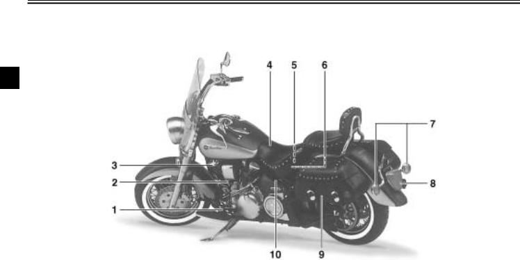
XV16A(C)/XV16AS(C) Left view
2
|
(XV16A) |
|||
|
1. Shift pedal |
(page 3-7) |
6. Helmet holder |
(page 3-12) |
|
2. Starter (choke) knob |
(page 3-11) |
7. Rear turn signal lights |
(page 6-35) |
|
3. Fuel cock |
(page 3-10) |
8. Tail/brake light |
(page 6-35) |
|
4. Rider seat |
(page 3-11) |
9. Fuses |
(page 6-32) |
|
5. Owner’s tool kit |
(page 6-2) |
2-1
DESCRIPTION
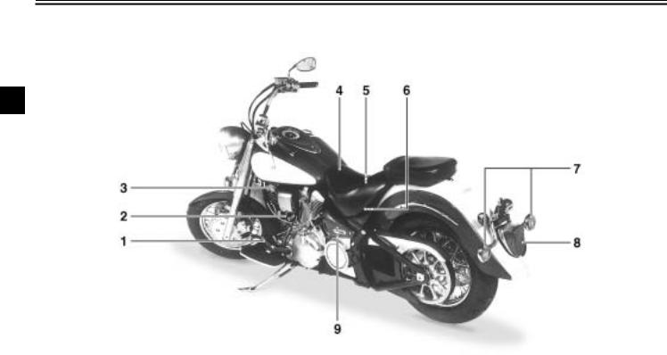
Road Star™
XV16A(C)/XV16AS(C) Right view
2
|
(XV16A) |
|||
|
10. Passenger footrest |
16. Brake pedal |
(page 3-8) |
|
|
11. Passenger seat |
17. Rider footrest |
||
|
12. Fuel tank |
(page 3-9) |
18. Shock absorber spring preload |
|
|
13. Fuel tank cap |
(page 3-8) |
adjusting nut |
(page 3-15) |
|
14. Headlight |
(page 6-33) |
19. Muffler |
|
|
15. Front turn signal/position lights |
(page 6-35) |
2-2
DESCRIPTION
Road Star™/Silverado™
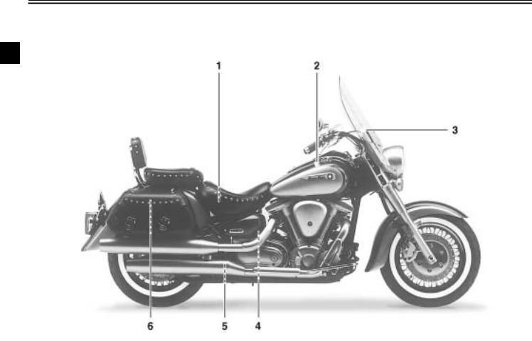
XV16AT(C) Left view
2
|
1. Shift pedal |
(page 3-7) |
6. Helmet holder |
(page 3-12) |
|
2. Starter (choke) knob |
(page 3-11) |
7. Rear turn signal lights |
(page 6-35) |
|
3. Fuel cock |
(page 3-10) |
8. Tail/brake light |
(page 6-35) |
|
4. Rider seat |
(page 3-11) |
9. Saddlebag |
(page 3-14) |
|
5. Owner’s tool kit |
(page 6-2) |
10. Fuses |
(page 6-32) |
2-3
![]()
DESCRIPTION
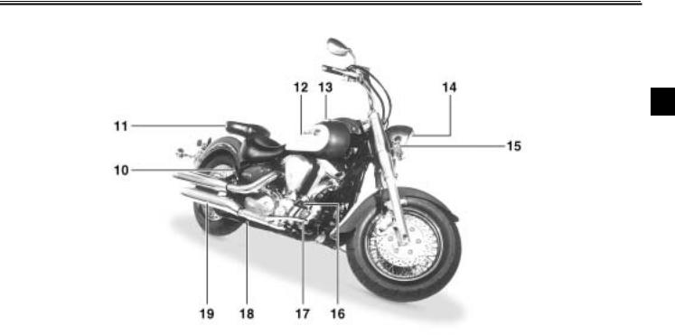
Road Star™/Silverado™
XV16AT(C) Right view
2
|
11. Passenger seat |
17. Brake pedal |
(page 3-8) |
|
|
12. Fuel tank |
(page 3-9) |
18. Rider footrest |
|
|
13. Fuel tank cap |
(page 3-8) |
19. Shock absorber spring preload |
|
|
14. Windshield |
(page 3-13) |
adjusting nut |
(page 3-15) |
|
15. Headlight |
(page 6-33) |
20. Passenger footrest |
|
|
16. Front turn signal/position lights |
(page 6-35) |
21. Muffler |
2-4

DESCRIPTION
Road Star™/Road Star™ Silverado™
XV16A(C)/XV16AS(C)/XV16AT(C) Controls and instruments
|
XV16A(C)/XV16AS(C) |
XV16AT(C) |
2
|
(XV16A) |
|||
|
1. Clutch lever |
(page 3-7) |
5. Right handlebar switches |
(page 3-6) |
|
2. Left handlebar switches |
(page 3-6) |
6. Throttle grip |
(page 6-17) |
|
3. Speedometer unit |
(page 3-3) |
7. Brake lever |
(page 3-7) |
|
4. Main switch/steering lock |
(page 3-1) |
2-5

INSTRUMENT AND CONTROL FUNCTIONS
|
Main switch/steering lock ………………………………. |
3-1 |
|
Indicator and warning lights ………………………….. |
3-2 |
|
Speedometer unit ………………………………………… |
3-3 |
|
Self-diagnosis device ……………………………………. |
3-4 |
|
Fuel gauge ………………………………………………….. |
3-4 |
|
Clock ………………………………………………………….. |
3-5 |
|
Handlebar switches ……………………………………… |
3-6 |
|
Clutch lever …………………………………………………. |
3-7 |
|
Shift pedal …………………………………………………… |
3-7 |
|
Brake lever ………………………………………………….. |
3-7 |
|
Brake pedal …………………………………………………. |
3-8 |
|
Fuel tank cap ………………………………………………. |
3-8 |
|
Fuel …………………………………………………………… |
3-9 |
||
|
Fuel cock ………………………………………………….. |
3-10 |
||
|
Starter (choke) knob ………………………………….. |
3-11 |
||
|
Locking the steering with a padlock ……………… |
3-11 |
||
|
Rider seat …………………………………………………. |
3-11 |
||
|
Helmet holder |
3-12 |
||
|
3 |
|||
|
Windshield [XV16AT(C)] |
3-13 |
||
|
…………………………….Saddlebags [XV16AT(C)] |
3-14 |
||
|
Adjusting the shock absorber assembly ………… |
3-15 |
||
|
Sidestand …………………………………………………. |
3-17 |
||
|
Ignition circuit cut-off system ……………………….. |
3-17 |
|
3-INSTRUMENT AND CONTROL FUNCTIONS |
EAU00027 |
3
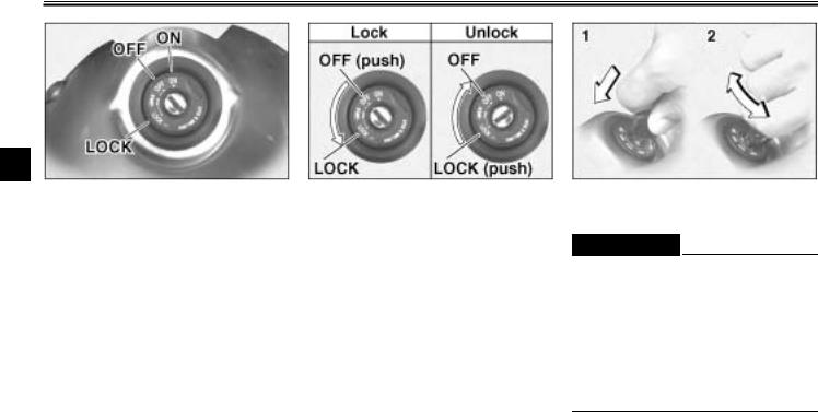
1. Push.
2. Turn.
Main switch/steering lock
The main switch/steering lock controls the ignition and lighting systems, and is used to lock the steering. The various positions are described below.
EAU00032
ON
All electrical systems are supplied with power, the headlight, meter lighting, taillight and front position lights come on, and the engine can be started. The key cannot be removed.
EAU00038
OFF
All electrical systems are off. The key can be removed.
LOCK
The steering is locked, and all electrical systems are off. The key can be removed.
To lock the steering
1.Turn the handlebars all the way to the left.
2.Push the key in from the “OFF” position, and then turn it to “LOCK” while still pushing it.
3.Remove the key.
To unlock the steering
Push the key in, and then turn it to “OFF” while still pushing it.
EW000016
 WARNING
@
Never turn the key to “OFF” or “LOCK” while the motorcycle is moving, otherwise the electrical systems will be switched off, which may result in loss of control or an accident. Make sure that the motorcycle is stopped before turning the key to “OFF” or “LOCK”.
@
3-1

INSTRUMENT AND CONTROL FUNCTIONS
1.Fuel level warning light “ ”
”
2.High beam indicator light “ ”
”
3.Turn signal indicator light “ ”
”
4.Neutral indicator light “  ”
”
5.Engine trouble warning light “  ”
”
EAU03034
Indicator and warning lights
EAU00079
Fuel level warning light “  ”
”
EAU00063
High beam indicator light “ ”
”
This indicator light comes on when the high beam of the headlight is switched on.
|
EAU00057 |
|||
|
Turn signal indicator light “ |
” |
||
|
This indicator light flashes |
when |
the |
3 |
|
turn signal switch is pushed to the left |
|||
|
or right. |
|||
|
EAU00061 |
|||
|
Neutral indicator light “ |
” |
This indicator light comes on when the transmission is in the neutral position.
EAU00091
Engine trouble warning light “  ”
”
This warning light comes on when the fuel level drops below approximately 0.9 US gal (0.8 Imp gal, 3.5 L). When this occurs, turn the fuel cock lever to the “RES” position and refuel as soon as possible.
This warning light comes on or flashes when an electrical circuit monitoring the engine is defective. When this occurs, have the Yamaha dealer check the self-diagnosis system.
3-2
INSTRUMENT AND CONTROL FUNCTIONS
3
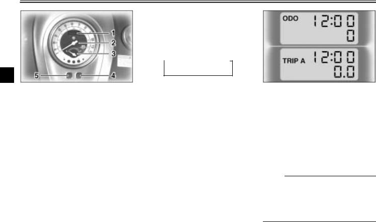
1.Odometer/tripmeter/clock
2.Speedometer
3.Fuel gauge
4.Set button
5.Mode button
EAU03393
Speedometer unit
The speedometer unit is equipped with a speedometer, an odometer and two tripmeters. The speedometer shows riding speed. The odometer shows the total distance traveled. The tripmeters show the distance traveled since they were last set to zero.
Pushing the mode button (left) switches the display between the odometer mode “ODO” and the tripmeter modes “TRIP A” and “TRIP B” in the following order:
CB-27E
 ODO
ODO TRIP A
 TRIP B
To reset a tripmeter, select it by pushing the mode button (left), and then hold down the set button (right) for at least one second. The tripmeters can be used to estimate the distance that can be traveled with a full tank of fuel. This information will enable you to plan future fuel stops.
NOTE:
@
This motorcycle is not equipped with a tachometer; however, it has a built-in engine speed limiter, which prevents the engine speed from exceeding approximately 4,400 r/min.
@
3-3
INSTRUMENT AND CONTROL FUNCTIONS
EAU01735
Self-diagnosis device
This model is equipped with a self-di- agnosis device for various electrical circuits.
If any of those circuits are defective, the engine trouble warning light will come on or the fuel level warning light will flash. If this occurs, have a Yamaha dealer check the motorcycle.
EC000004
CAUTION:
@
When the tachometer displays an error code, the motorcycle should be checked as soon as possible in order to avoid engine damage.
EAU00113
Fuel gauge
The fuel gauge indicates the amount of fuel in the fuel tank. The needle moves towards “E” (Empty) as the fuel level decreases. When the needle reaches “E”, refuel as soon as possible.
Do not allow the fuel tank to empty itself completely.
@
@
3-4

INSTRUMENT AND CONTROL FUNCTIONS
3
1.Clock
2.Set button
3.Mode button
EAU01736
Clock
The digital clock shows the time regardless of the main switch position.
To set the clock:
1.Turn the key to “ON”.
2.Press both the set button (right) and the mode button (left) simultaneously until the hours and minutes flash.
4.Push the right button to change the hours.
5.Push the left button and only the minute display will flash.
6.Push the right button to change the minutes.
7.Push the left button and both the hours and minutes will flash.
3.Push the left button and only the hour display will flash.
8.Push the right button for two seconds to set the clock.
3-5
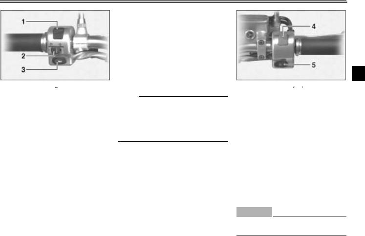
INSTRUMENT AND CONTROL FUNCTIONS
1.Dimmer switch “ /
/  ”
”
2.Turn signal switch “ ”
”
3.Horn switch “  ”
”
EAU00118
Handlebar switches
EAU03888
Dimmer switch “ /
/  ”
”
Set this switch to “ ” for the high beam and to “
  ” for the low beam.
EAU04078
Turn signal switch “  /
/  ”
”
To signal a right-hand turn, push this switch to the right. To signal a left-hand turn, push this switch to the left. When released, the switch returns to the center position.
Since this model is equipped with a self-canceling system, the turn signal lights will self-cancel after the motorcycle has traveled both about 150 m (490 ft) and for approximately 15 seconds. However, the turn signal lights can also be canceled manually by pushing the switch in after it has returned to the center position.
NOTE:
_
The self-canceling system only operates when the motorcycle is moving, so that the turn signal lights will not selfcancel while you are stopped at an intersection.
_
EAU00129
Horn switch “  ”
”
Press this switch to sound the horn.
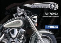
3
4.Engine stop switch “  /
/  ”
”
5.Start switch “  ”
”
EAU03890
Engine stop switch “  /
/  ”
”
Set this switch to “  ” before starting the engine. Set this switch to “
  ” to stop the engine in case of an emergency, such as when the motorcycle overturns or when the throttle cable is stuck.
EAU00143
Start switch “  ”
”
Push this switch to crank the engine with the starter.
EC000005
CAUTION:
@
See page 5-1 for starting instructions prior to starting the engine.
@
3-6

INSTRUMENT AND CONTROL FUNCTIONS
3
1. Clutch lever
EAU00152
Clutch lever
The clutch lever is located at the left handlebar grip. To disengage the clutch, pull the lever toward the handlebar grip. To engage the clutch, release the lever. The lever should be pulled rapidly and released slowly for smooth clutch operation.
The clutch lever is equipped with a clutch switch, which is part of the ignition circuit cut-off system. (See page 3-17 for an explanation of the ignition circuit cut-off system.)
1. Shift pedal
EAU01215
Shift pedal
The shift pedal is located on the left side of the engine and is used in combination with the clutch lever when shifting the gears of the 5-speed con- stant-mesh transmission equipped on this motorcycle.
NOTE:
@
Use your toes or heel to shift up and your toes to shift down.
@
1. Brake lever
EAU00158
Brake lever
The brake lever is located at the right handlebar grip. To apply the front brake, pull the lever toward the handlebar grip.
3-7
![]()
INSTRUMENT AND CONTROL FUNCTIONS
1. Brake pedal
EAU00162
Brake pedal
The brake pedal is on the right side of the motorcycle. To apply the rear brake, press down on the brake pedal.
1.Fuel tank cap lock cover
2.“ ” mark
a.Unlock.
b.Lock.
EAU02917
Fuel tank cap
To remove the fuel tank cap
Slide the lock cover open, insert the key into the lock, and then turn it 1/4 turn clockwise. The lock will be released and the fuel tank cap can be removed.
To install the fuel tank cap
1.Insert the fuel tank cap into the
tank opening with the key inserted in the lock and with the “ ” mark facing forward.
2.Turn the key counterclockwise to the original position, remove it,
|
and then close the lock cover. |
3 |
NOTE:
@
The fuel tank cap cannot be installed unless the key is in the lock. In addition, the key cannot be removed if the cap is not properly installed and locked.
@
EW000024
 WARNING
@
Make sure that the fuel tank cap is properly installed before riding.
@
3-8

INSTRUMENT AND CONTROL FUNCTIONS
3
1.Fuel tank filler tube
2.Fuel level
EAU03753
Fuel
Make sure that there is sufficient fuel in the tank. Fill the fuel tank to the bottom of the filler tube as shown.
EW000130
 WARNING
_
●Do not overfill the fuel tank, otherwise it may overflow when the fuel warms up and expands.
●Avoid spilling fuel on the hot engine.
_
EAU00185
CAUTION:
@
Immediately wipe off spilled fuel with a clean, dry, soft cloth, since fuel may deteriorate painted surfaces or plastic parts.
@
EAU04194
Recommended fuel:
UNLEADED GASOLINE ONLY Fuel tank capacity:
Total amount:
5.3 US gal (4.4 Imp gal, 20 L) Reserve amount:
0.9 US gal (0.8 Imp gal, 3.5 L)
ECA00102
CAUTION:
_
Use only unleaded gasoline. The use of leaded gasoline will cause severe damage to the engine internal parts such as valves, piston rings, exhaust system, etc.
_
Your Yamaha engine has been designed to use regular unleaded gasoline with a pump octane number [(R+M)/2] of 86 or higher, or a research octane number of 91 or higher. If knocking (or pinging) occurs, use a gasoline of a different brand or premium unleaded fuel. Use of unleaded fuel will extend spark plug life and reduce maintenance costs.
Gasohol
There are two types of gasohol: gasohol containing ethanol and that containing methanol. Gasohol containing ethanol can be used if the ethanol content does not exceed 10%. Gasohol containing methanol is not recommended by Yamaha because it can cause damage to the fuel system or vehicle performance problems.
3-9

INSTRUMENT AND CONTROL FUNCTIONS
|
OFF: closed position |
ON: normal position |
Pointed end positioned over “OFF”
EAU03050
Fuel cock
The fuel cock supplies fuel from the tank to the carburetor while filtering it also.
The fuel cock has three positions:
OFF
With the lever in this position, fuel will not flow. Always return the lever to this position when the engine is not running.
Pointed end positioned over “ON”
ON
With the lever in this position, fuel flows to the carburetor. Normal riding is done with the lever in this position.
RES: reserve position
3
Pointed end positioned over “RES”
RES
This indicates reserve. If you run out of fuel while riding, move the lever to this position. Fill the tank at the first opportunity. Be sure to set the lever back to “ON” after refueling!
3-10

INSTRUMENT AND CONTROL FUNCTIONS
3
EAU04038
Starter (choke) knob “ 

 ”
”
Starting a cold engine requires a richer air-fuel mixture, which is supplied by the starter (choke).
Move the knob in direction a to turn on the starter (choke).
Move the knob in direction b to turn off the starter (choke).
EAU03372
Locking the steering with a padlock
In addition to the main switch/steering lock, there are brackets on the right side of the steering head pipe for locking the steering with a padlock. To do so, turn the handlebar until the holes in the two brackets are aligned, and then lock the steering with a suitable padlock.
EAU03785*
Rider seat
To remove the rider seat
1.Insert the key into the main switch, and then turn it counterclockwise to “OPEN”.
NOTE:
_
Do not push inward when turning the key.
_
2. Pull the rider seat off.
3-11

INSTRUMENT AND CONTROL FUNCTIONS
1.Projection
2.Seat holder
To install the rider seat
1.Insert the projection on the rear of the rider seat into the seat holder as shown, and then push the front of the seat down to lock it in place.
2.Remove the key from the main switch if the motorcycle will be left unattended.
NOTE:
_
Make sure that the rider seat is properly secured before riding.
_
1. Helmet holder
EAU00264
Helmet holder
The helmet holder is located under the rider seat.
To secure a helmet to the helmet holder
1.Remove the rider seat. (See page 3-11 for rider seat removal and installation procedures.)
2.Attach the helmet to the helmet holder, and then securely install the seat.
EW000030
 WARNING
_
Never ride with a helmet attached to the helmet holder, since the helmet may hit objects, causing loss of control and possibly an accident.
_
To release the helmet from the hel- 3 met holder
Remove the rider seat, remove the helmet from the helmet holder, and then install the seat.
3-12

INSTRUMENT AND CONTROL FUNCTIONS
3
1.Windshield
2.Bolt (× 4)
EAU01231
Windshield [XV16AT(C)]
To suit the rider’s preference, the windshield angle can be adjusted and the height can be changed to one of two positions.
To adjust the windshield angle
1.Loosen the bolts on each side of the windshield.
2.Move the windshield to the desired angle.
3.Tighten the bolts to the specified torque.
1.Headlight cover
2.Screw (× 4)
To change the windshield height
1.Remove the bolts on each side of the windshield.
2.Move the windshield to the other position.
3.Install the bolts and tighten them to the specified torque.
Tightening torque: Windshield bolts:
12 ft·lb (1.6 m·kgf, 16 Nm)
4.Loosen the screws holding the windshield cover located above the headlight, position the cover close to the headlight without touching it, and then tighten the screws.
3-13
 Loading…
Руководство по эксплуатации и техническому обслуживанию мотоциклов Yamaha XV1600A Wild Star.
- Издательство: Yamaha Motor Co., Ltd.
- Год издания: 2001
- Страниц: 114
- Формат: PDF
- Размер: 9,2 Mb
Руководство по эксплуатации и техническому обслуживанию мотоциклов Yamaha XV1600A Wild Star.
- Издательство: Yamaha Motor Co., Ltd.
- Год издания: 2001
- Страниц: 114
- Формат: PDF
- Размер: 9,2 Mb
Руководство по эксплуатации и техническому обслуживанию мотоциклов Yamaha XV1600A Wild Star.
- Издательство: Yamaha Motor Co., Ltd.
- Год издания: 2001
- Страниц: 114
- Формат: PDF
- Размер: 9,2 Mb

Сборник руководств на английском языке по эксплуатации и техническому обслуживанию мотоциклов Yamaha моделей XV16 Road Star, XV17 Road Star (Road Star Warrior, Star), XV19 Roadliner (Star), XV125S Virago, XV250 Star (Virago), XV535 Virago, XV750K, XV1100 Virago, XV1600A Wild Star, XV1700 Road Star Warrior и XV1900 MidnightStar (Roadliner) различных модификаций.
- Издательство: Yamaha Motor Co., Ltd.
- Год издания: —
- Страниц: —
- Формат: PDF
- Размер: 164,0 Mb
Руководство на английском языке по ремонту мотоциклов Yamaha моделей XV16AL, XV16ALC, XV16ATL и XV16ATLC.
- Издательство: Yamaha Motor Co., Ltd.
- Год издания: 1998
- Страниц: 449
- Формат: PDF
- Размер: 10,3 Mb
Руководство на английском языке по ремонту мотоциклов Yamaha моделей XV19SW(C), XV19W(C), XV19MW(C), XV19CTSW(C), XV19CTW(C) и XV19CTMW(C).
- Издательство: Yamaha Motor Co., Ltd.
- Год издания: 2006
- Страниц: 444
- Формат: PDF
- Размер: 19,4 Mb
Руководство на английском языке по ремонту мотоциклов Yamaha моделей XV19SX(C), XV19MX(C), XV19CTSX(C), XV19CTMX(C), XV19CSX(C) и XV19CX(C) Star 2008 года выпуска.
- Издательство: Yamaha Motor Co., Ltd.
- Год издания: 2007
- Страниц: 494
- Формат: PDF
- Размер: 29,4 Mb
Руководство на английском языке по ремонту мотоциклов Yamaha XV250.
- Издательство: Yamaha Motor Co., Ltd.
- Год издания: 1994
- Страниц: 291
- Формат: PDF
- Размер: 33,4 Mb
Руководство на испанском языке по ремонту мотоциклов Yamaha XV-250S.
- Издательство: Yamaha Motor da Amazonia Ltda.
- Год издания: 1997
- Страниц: 265
- Формат: PDF
- Размер: 31,7 Mb
Руководство на английском языке по ремонту мотоциклов Yamaha XV500K.
- Издательство: Yamaha Motor Co., Ltd.
- Год издания: —
- Страниц: —
- Формат: HTM
- Размер: 11,1 Mb
Руководство на испанском языке по ремонту мотоциклов Yamaha XV535.
- Издательство: Yamaha Motor do Brasil Ltda.
- Год издания: 1999
- Страниц: 281
- Формат: PDF
- Размер: 5,9 Mb
Руководство на английском языке по техническому обслуживанию и ремонту мотоциклов Yamaha моделей XV535, XV700, XV750, XV920, XV1000 и XV1100 Virago 1981-1994 годов выпуска.
- Издательство: Haynes Publishing
- Год издания: 1994
- Страниц: 363
- Формат: PDF
- Размер: 48,3 Mb
Руководство на английском языке по техническому обслуживанию и ремонту мотоциклов Yamaha моделей XV535-1100 Virago 1981-2003 годов выпуска.
- Издательство: Clymer
- Год издания: 2004
- Страниц: 511
- Формат: PDF
- Размер: 52,8 Mb
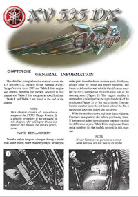
Руководство на английском языке по техническому обслуживанию и ремонту мотоциклов Yamaha XV535DX Virago.
- Издательство: —
- Год издания: —
- Страниц: 211
- Формат: PDF
- Размер: 37,4 Mb
Сборник руководств на английском языке по ремонту мотоциклов Yamaha моделей XV1700P, XV1700PC, XV1700PCR и XV1700PCRC.
- Издательство: Yamaha Motor Co., Ltd.
- Год издания: 2001/2002
- Страниц: 515/605
- Формат: PDF
- Размер: 42,2 Mb

![]()
4-я Красноармейская, 2А
Санкт-Петербург, 190005
Email: info@lenmoto.ru
Телефон: +7 (921) 930-81-18
Телефон: +7 (911) 928-08-06
Компания ЛенМото
Запчасти, аксессуары, экипировка, тюнинг для мотоциклов, скутеров, квадроциклов, снегоходов, багги, гидроциклов, катеров и лодочных моторов.
Подпишитесь на наши новости
Подписаться
Подборка мануалов на чопперы Yamaha. Какие-то на русском языке, какие-то на английском.
Если у вас есть мануал, которого нет у нас — пишите в личку, добавим в коллекцию
Ниже — ссылки на скачку мануалов. Ссылки на скачивание доступны только зарегистрированным пользователям.
Мануалы все в PDF, просматривать можно через бесплатную прогу с русским интерфейсом Adobe Acrobat, например. Авторские права не нарушаются, мануалы распространяются правообладателями бесплатно и находятся в открытом доступе. Все права на мануалы принадлежат компании Yamaha.
Большая часть мануалов есть на русском языке, остальные — на английском. Итак, список:
Yamaha Drag Star (V-Star) XVS 650
Yamaha Drag Star (V-Star) XVS 650
Yamaha XV 1700 Road Star Warrior
Yamaha XV 1600 Road Star (Wild Star)
Yamaha XV 1700 Road Star
Yamaha XVS 1300 Midnight Star
Yamaha XVS 950 Midnight Star
Yamaha XV 950 Bolt
Yamaha XV 1900 Raider
Yamaha XV 1900 Roadliner & Stratoliner. На Midnight Star 1900 тоже должны подходить.
Yamaha VMX1200 V-Max
Yamaha Virago XV250
Yamaha Virago XV400 / XV535
Yamaha XV750 / XV1100
Yamaha XVS 1300 Stryker
Yamaha XVZ13 (XVZ 1300) Royal Star
Yamaha XVZ13 (XVZ1300) Venture Royale (’85-далее)
Ссылки — ниже, они доступны зарегистрированным пользователям.
Скрытый текст. Необходимо зарегистрироваться.